Cisco CCNA Cyber Ops SECFND 210-250, Section 11: Understanding Network Security Technologies
11.2 Defense-in-Depth Strategy
11.3 Defend Across the Attack Continuum
11.4 Authentication, Authorization, and Accounting
11.5 Identity and Access Management
11.6 Stateful Firewall
11.7 Network Taps
11.8 Switched Port Analyzer
11.9 Remote Switched Port Analyzer
11.10 Intrusion Prevention System
11.
11.
11.
11.
11.
11.
11.
11.
11.
11.
11.
11.
11.
Defense-in-Depth Strategy
It is often said that the security of a system is only as strong as its weakest link. Although this is a fairly universal concept, it is rarely addressed by security designers. The complexity of today’s systems makes it difficult to identify all the weak links, let alone the weakest link.
Defense in depth can be considered a building block of other security design principles. This guideline calls for applying a layered approach to security, and it is aimed at providing redundant controls at multiple levels to mitigate risk.
This same strategy was used in medieval castles to provide multiple layers of defense to resist lengthy sieges. In addition to multiple layers of walls (perimeters), a medieval castle used an array of protection mechanisms, which often complemented each other (such as a moat, a drawbridge, bastion towers, an outer courtyard, an inner court, and an inner keep).

Defense in depth is a philosophy that provides layered security to a system by using multiple security mechanisms and generally follows these principles:
- Security mechanisms should back each other up and provide diversity and redundancy of protection.
- Security mechanisms should not depend on each other, so that their security does not depend on other factors that are outside their control.
- Using defense in depth, you can eliminate single points of failure and augment weak links in the system to provide stronger protection with multiple layers.
While the concept of defense-in-depth is intuitive, the complexity of modern systems can make its implementation difficult. Modern systems may be distributed across multiple processes running within and between computational systems dispersed across the intranet, extranet, and the Internet using various physical and virtual resources. An analogy that is commonly used to describe the defense-in-depth strategy is an onion because it implies the use of multiple embedded layers.
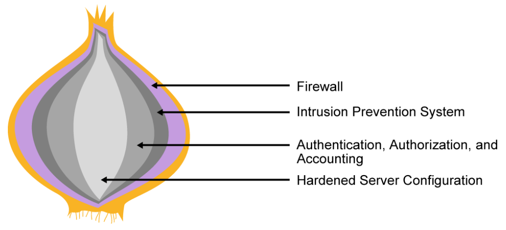
However, because of the distribution of resources, network defenses cannot surround all components. With modern distributed systems, an artichoke often makes a better analogy than an onion. While protections do overlap each other, like the petals of an artichoke, the compromise of a single defense can often be used as a stepping stone to compromise other parts of the distributed system.
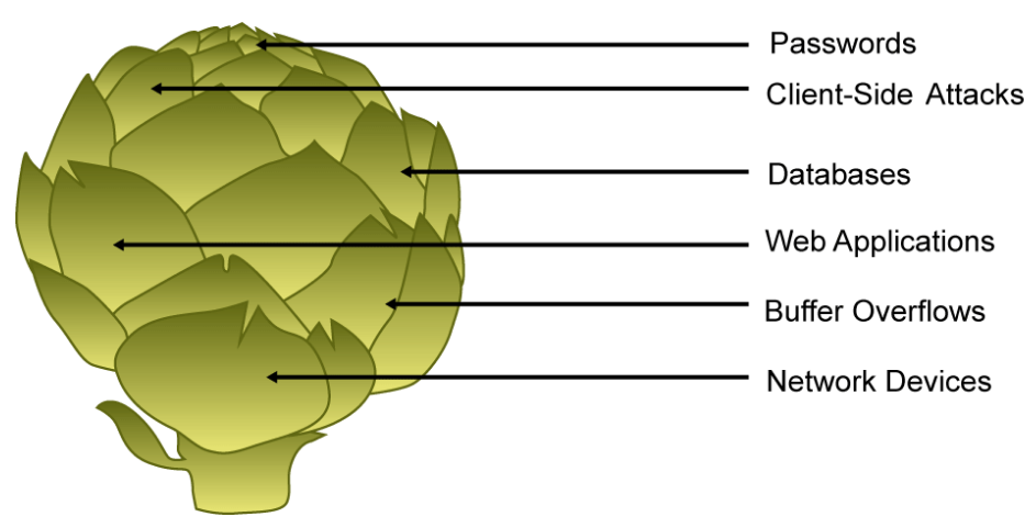
Defense in depth minimizes the probability that the efforts of malicious hackers will succeed. If an attacker gains access to the network, defense in depth minimizes the adverse impact and gives security administrators and analysts time to deploy new or updated countermeasures to prevent recurrence.
Various components will be involved to implement the strategy of defense in depth successfully, such as firewalls, intrusion prevention systems, advanced malware protection, web content security systems, email content security systems, identity services, network access controls and so on. In addition to the protection provided by these components, it is also important to physically protect business sites along with comprehensive and ongoing personnel training because it enhances the security of vital data against compromise, theft, or destruction.
Defend Across the Attack Continuum
The industrialization of cybercrime has increased the threat landscape. Security has evolved from classic perimeter defenses to a thorough, pervasive, and actionable model. Modern security solutions should be able to secure any device, across any network, to any application, and must address the network security challenges from the perspective of the attack continuum.
The attack continuum is divided into three phases: before, during, and after. Understanding these phases is important because this continuous model is consistent with how companies secure, defend, and audit networks on a day-to-day basis, and can help analysts to suggest better solutions that provide protection throughout the attack continuum. The best way to communicate the totality of the security challenge is by looking at the attack continuum while trying to defend the network. The reason to use this security model is to accentuate that a silver bullet is not feasible nor possible.
Today’s threat landscape is nothing like it was just a few years ago. Simple attacks that caused containable damage have given way to modern cybercrime operations that are sophisticated, well-funded, and capable of causing major disruptions to organizations and the national infrastructure. Not only are these advanced attacks difficult to detect, they remain in networks for long periods of time and amass network resources to launch attacks elsewhere.
Traditional defenses that rely exclusively on detection and blocking for protection are no longer adequate. Most security tools today focus on providing visibility into the network and blocking malware at the point of entry. They scan files once at an initial point in time to determine whether they are malicious. But advanced attacks do not occur at a single point in time; they are ongoing and require continuous scrutiny. Adversaries now employ tactics such as port hopping, encapsulation, zero-day attacks, command and control detection evasion, sleep techniques, lateral movement, encrypted traffic, blended threats, and sandbox evasion to elude initial detection. If the file is not caught or if it evolves and becomes malicious after entering the environment, point-in-time detection technologies cease to be useful in identifying the unfolding follow-on activities of the attacker.
Security methods cannot only focus on detection—they must also include the ability to mitigate the impact once an attacker gets in. Organizations need to look at their security model holistically and gain visibility and control across the extended network and the full attack continuum: before an attack happens, during the time it is in progress, and even after it begins to damage systems or steal information. Today’s network security controls should work across the attack continuum. Using a threat-centric security model addresses the full attack continuum, across all attack vectors as shown in the figure below.
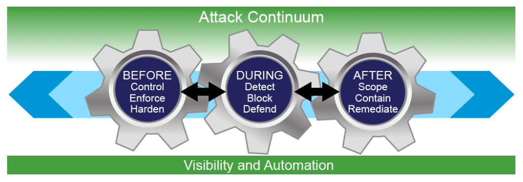
- Before: You need to know what you are defending. A device inventory of your network (devices, OS, services, applications, users, and so on.), is important to be able to defend it. You need to implement access controls, enforce policy, and block applications and overall access to assets which will reduce the scope of the network’s attackable surface space, which expends a company’s time and money. Unfortunately, attackers have a relatively easy time penetrating the network perimeter even with good access controls. Before an attack, solutions that include firewalls, NGFWs, NAC, and identity services, give security professionals the tools that they need to discover threats and enforce and harden policies.
- During: When attacks get through, you need to be able to detect them. You must have the best threat detections available. Once an attack is detected, you can block it and defend the environment. During an attack, NGIPSs, email, and web security solutions help detect, block, and defend against attacks that have penetrated the network and are in progress.
- After: Invariably, attacks will be successful and you will need to determine the scope of the damage, contain the event, remediate, and bring operations back to normal. You also need to address a broad range of attack vectors with solutions that operate everywhere a threat can manifest itself. After an attack, organizations can leverage solutions such as AMP, SIEM, and network behavior analysis, to quickly and effectively scope, contain, and remediate an attack to minimize damage.
To overcome today’s security challenges and gain better protection, organizations need solutions that span the entire attack continuum and are designed based on the tenets of being visibility-driven, threat-focused and platform-based. For example, Cisco offers a comprehensive portfolio of threat-centric cybersecurity solutions that span the entire attack continuum.
Authentication, Authorization, and Accounting
AAA plays an important role in how almost all networks are accessed today. AAA is an architectural framework for consistently configuring a set of three independent modular security functions: authentication, authorization, and accounting.
- Authentication: Provides the method of identifying users, including login and password dialog, challenge and response, messaging support, and, depending on the security protocol you select, encryption. Authentication identifies a user before allowing the user access to the network.
- Authorization: Defines what an individual or groups of identities are allowed to do once authenticated, including one-time authorization or authorization for each service, per-user account list and profile, user group support, and support of IP, console commands, network connections, and Telnet and reverse Telnet connections. AAA authorization works by assembling a set of attributes that describe what the user is authorized to perform. These attributes are compared to the information contained in a database for a given user and the result is returned to AAA to determine the user's actual capabilities and restrictions. The database can be located locally on the access server or router or it can be hosted remotely on a RADIUS or TACACS+ security server. Remote security servers, such as RADIUS and TACACS+, authorize users for specific rights by associating AV pairs, which define those rights with the appropriate user.
- Accounting: Keeps track of what individual identities have done. Accounting is a method for collecting and sending security server information that is used for billing, auditing, and reporting, such as user identities, start and stop times, executed commands, and number of packets and bytes. Accounting enables you to track the services users are accessing as well as the amount of network resources they are consuming. When AAA accounting is activated, the network access server reports user activity to the RADIUS or TACACS+ security server (depending on which security method you have implemented) in the form of accounting records. Each accounting record is composed of accounting AV pairs and is stored on the access control server. This data can then be analyzed for network management, client billing, and/or auditing.
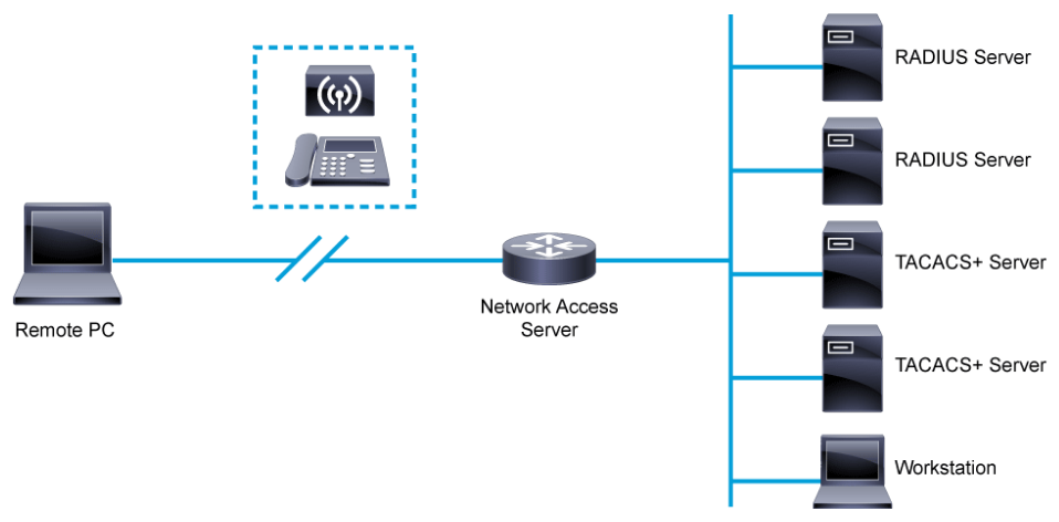
AAA can be associated with network access and with administrative access. For example, in the figure above, using a remote access VPN client to connect to the corporate network from a remote location is considered network access. When connecting this way, the user is challenged for credentials to log on to the VPN. This logon process in AAA terms is the authentication method. Depending on the user’s department, the user may be allowed or denied access to certain resources via the VPN. This process in AAA terms is the authorization method. Lastly, details of the session, such as dates and times, remote IP address, and systems that are accessed may be logged. This process in AAA terms is the accounting method.
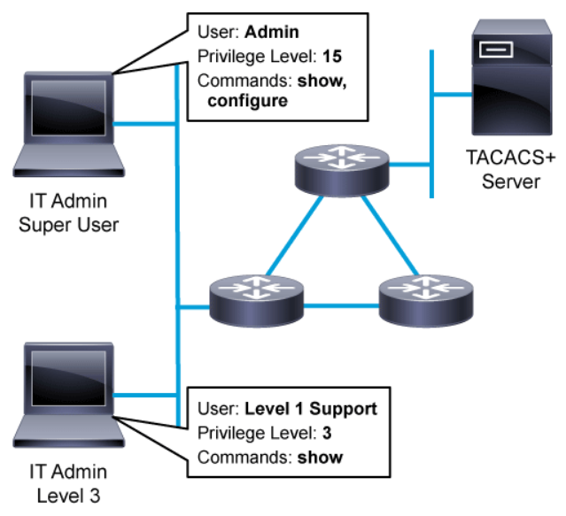
Similarly, AAA can control access and authorization methods for device-level administration. In the above figure, a staff member of the IT department may log in to the router to make a configuration change. The configure command is typically associated with privilege level 15 and is considered administrative access. Another member of the IT staff, a more junior administrator logs in and is granted level 3 access which only grants her the ability to use show commands for basic device troubleshooting. Both IT staff members must authenticate to the network devices they are accessing. Depending on the login, the IT administrator may have limited or no access to configuration commands. For example, members of the network operations team may be allowed to modify the SNMP configuration on the router, but not modify routing protocol configuration. The level of command access is determined by the configured AAA authorization method. Finally, the details of the administrative session may be logged. The details may include session start and stop times and commands that were entered.
AAA method data must be stored somewhere. The simplest implementation of AAA is to use the local database on individual network devices. In this implementation, AAA authentication and authorization data are stored directly in the device’s configuration. While this approach is simplest to configure, using the local AAA database does not scale in large network environments. User name and password definitions as well as authorization specifications must be configured and maintained on every network device. Imagine password management where passwords must be updated independently on hundreds or thousands of devices. Also, understand that configuring user names and passwords in the local database is an administrative act. When a remote access VPN system is configured with local AAA, users do not normally select their passwords. Instead their passwords are assigned by an administrator. Another shortcoming of local AAA is that it does not support accounting methods. AAA accounting data can build up very quickly and network devices simply do not have enough persistent storage to support local AAA accounting.
In all but the smallest deployments, centralized AAA is preferred over local AAA. With centralized AAA, configuration and maintenance of AAA policy is more manageable. Authentication and authorization methods are defined and managed centrally and made available to all devices in the network. Beyond the initial configuration, maintenance is also simplified. If an authorization policy is changed in the centralized system, the change is inherited by all devices. Centralized AAA also enables the use of the Accounting method. Accounting records from all devices are sent to centralized repositories enabling simplified auditing of accounting records.
A centralized AAA system may independently maintain databases for authentication, authorization, and accounting. However, it is most common for the AAA system to leverage existing user repositories for authentication. For example, if an organization uses Active Directory or LDAP, those systems provide robust user repositories with sophisticated password management features. A centralized AAA system may leverage Active Directory or LDAP for user authentication and group membership, while maintaining its own authorization and accounting databases.
Whether the AAA implementation is centralized on servers or configured locally on network devices, AAA implementations use protocols to enable AAA methods. Generally, an individual network device is considered an AAA client and the systems that they communicate with are considered AAA servers. The two AAA protocols that are commonly implemented in today’s IP-based networks are RADIUS and TACACS+.
TACACS+ vs. RADIUS comparisons:
- RADIUS uses UDP ports (1812 for authentication and 1813 for accounting) (or 1645 and 1646 respectively).
- RADIUS combines authentication and authorization.
- RADIUS encrypts only the password in the access-request packet, from the client to the server. The remainder of the packet is unencrypted. Other information, such as username, authorized services, and accounting, can be captured by a third party.
- TACACS+ uses TCP port 49.
- TACACS+ separates authentication, authorization, and accounting.
- TACACS+ encrypts the entire body of the packet but leaves a standard TACACS+ header. Within the header is a field that indicates whether the body is encrypted or not. For debugging purposes, it is useful to have the body of the packets unencrypted. However, during normal operation, the body of the packet is fully encrypted for more secure communications.
Identity and Access Management
The concept of a traditional enterprise network perimeter has continued to break down over time. To remain productive in today’s competitive marketplace, employees now insist on using mobile devices to work anytime and anywhere. The average user has three devices accessing the corporate network. More connected devices mean a continued expansion of the attack surface that enterprises need to secure. In addition, enterprises have increased their use of SaaS and virtualization, making it increasingly difficult to securely authenticate and authorize users seeking access to corporate resources. Therefore, IT departments have to strike a delicate balance between maintaining security of networks, systems, and applications, and the productivity of enterprise employees.
A different approach is required for both the management and security of the evolving mobile enterprise. With superior user and device visibility, the IAM solution delivers simplified mobility experiences to enterprises. The IAM solution allows security analysts to see and control users and devices connecting to the corporate network from a central location.

IAM solutions let you supplement existing authentication and authorization policy attributes with contextual network information. Contextual network information allows an appropriate level of challenge measures to be taken during the authentication process including the ability to adapt these challenges to the perceived level of risk. This level of precision in authentication and application authorization decisions is critical to safeguard information assets and decrease the risk of a cyber attack. Some of the main attributes available for use by IAM platforms for user- and device-related context include:
- User: User name, IP address, authentication status, location
- User class: Authorization group, guest, quarantined
- Device: Manufacturer, model, OS, OS version, MAC address, IP address, network connection method (wired or wireless), location
- Posture: Posture when discussing identity and access management refers to the compliance status of the endpoint device including antivirus is installed, antivirus at correct version, OS patch level, and other device posture compliance status data.
When contextual network attributes are used by identity and access management solutions, network access security is enhanced by the following benefits:
- Accurate identification of every user and device
- Easy device provisioning
- Centralized policy management to control user access: whoever, wherever, and from whatever device
- Flexible integration with other solutions to speed threat detection, containment, and remediation
The diagram below depicts the general flow of IAM policy decisions when an endpoint attempts to access the network.
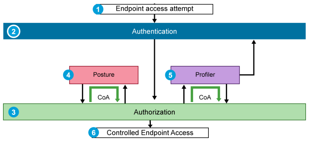
- The endpoint attempts network access via a NAD.
- The user is challenged to authenticate via a technology such as 802.1x. Successful authentication identifies the user of the endpoint.
- Based on the characteristics of the authentication process, an authorization policy is selected and communicated to the NAD, leading to controlled endpoint access.
- If posturing services are deployed, the authorization profile that is selected immediately after authentication does not normally provide full network access. Posture assessment can then begin. If the endpoint is determined to be compliant with the organization security policy, then a more permissive authorization policy can be assigned to the session. To convey the change in policy to the NAD, a CoA message is sent.
- Similarly, profiler services also make use of CoA. If a profiler is deployed, and a new endpoint connects for the first time, the authorization profile will be one that is associated with unknown devices. After profiling is completed and the endpoint classification is identified, a new authorization policy can be assigned to the session. The new authorization policy is communicated to the NAD using a CoA message. The results of profiler probes are stored in the Security appliance's internal endpoint database. The endpoint MAC address is the key field in the database entry and uniquely identifies the endpoint. On subsequent access attempts from this endpoint, the endpoint classification from the last profiler update is available as additional context for the initial authorization assignment decision.
- Based on the results of the above processes, the endpoint is given appropriate authorization for network access.
An example of an IAM solution is the Cisco Identity Services Engine (Cisco ISE). The figure below shows sample log information from Cisco ISE that is related to authentication.
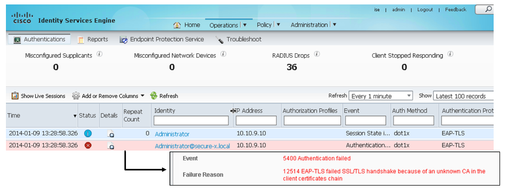
In this example, you see a failed authentication attempt. The EAP-TLS handshake failed because of an unknown CA in the client certificates chain.
EAP-TLS based authentication is considered more secure because both the server and the client will use certificates for authentication. The server (Cisco ISE in this example) verifies the client certificate against the CA root certificates list. To make the authentication process more secure, a private CA will usually be deployed in the enterprise to provide certificates only for the legitimate users and devices in their domain. These certificates ensure that any connection attempts by unauthorized users or attackers will be denied.
The log message that is generated in this example is likely due to an attacker attempting to connect to the network, and the client certificate and the signature of the attacker could not be verified against the CA root certificate list. This error could also appear if the client certificate of the attacker was revoked and the attacker attempts to connect to the network.
This type of log message does not always mean that there is an attacker trying to connect to the network. This message might be generated when a legitimate user who has yet to obtain a certificate from the CA tries to connect to the network. But, if more log messages with the same error message appear, as a security analyst, view the detailed logs and find the NAD to which the user or endpoint is connected. After that, verify whether the user who is trying to connect to the network is a legitimate user or not. In this way, understanding the traffic flow of IAM solutions can help the security analyst to narrow down the issue when interpreting log messages and thus take appropriate actions.
Stateful Firewall
A firewall is a network security device that monitors the incoming and outgoing network traffic and decides whether to allow or block the traffic based on a defined set of security rules. Firewalls have been a first line of defense in network security for many years. Firewalls establish a barrier between the secured and controlled internal networks that can be trusted, and the untrusted outside networks, such as the Internet.
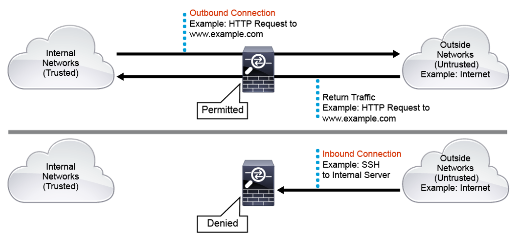
As shown in the figure below, by default, a firewall such as the Cisco Adaptive Security Appliance (Cisco ASA) will permit and inspect the traffic that is initiated from the internal trusted networks and is destined to the outside untrusted networks. The Cisco ASA will also automatically permit the corresponding return traffic from the outside networks back to the internal networks. But any traffic that is initiated from the outside networks and is destined to the internal networks is denied by default.
Security analysts should understand how firewalls function and how to interpret firewall logs when performing incident investigations. Usually, you can assume that the attack traffic must have traveled through a firewall somewhere on the network. Therefore, examining the firewall logs may give insight to the characteristics of the attack traffic.
Stateful Firewall Basic Operations
Where a stateless packet filter, such as an ACL, accesses on a packet-by-packet basis, a stateful firewall allows or blocks traffic based on the connection state, port, and protocol. Stateful firewalls inspect all activity from the opening of a connection until the connection is closed. Data that is associated with each connection is stored in the firewall connection’s state table.
Stateful firewalls can also provide stateful inspection of applications that use a control channel to facilitate the dynamically negotiated data connection. The FTP protocol is an example that uses a control and data channel.
For example, using the FTP active mode, the FTP client connects to the FTP server on TCP port 21, which is the control channel. For the FTP client to requests data, the FTP client specifies a dynamic TCP port number for the FTP server to use for the data channel (TCP port 2010 in the example as shown in the figure below). The FTP server then initiates the data connection from source TCP port 20 to the destination TCP port specified by the FTP client (TCP port 2010 in the example as shown in the figure below).
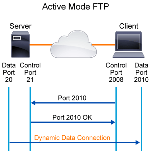
Stateful firewall monitors the control channel of the FTP sessions. When a data connection is negotiated between the FTP client and the FTP server, the stateful firewall populates its connections state table with an entry to allow that dynamic data connection.
The following output shows an example of the Cisco ASA connections state table. In this example, 192.168.1.3 is the FTP client on the inside trusted network, and the 209.165.202.130 host is the FTP server on the outside untrusted network. The Cisco ASA maintains connection state flags for each connection. For example, the UIO flag indicates that the TCP connection is up and sending inbound and outbound data. The B flag means that the connection was initiated from the outside. Examining the FTP command channel (port 21) and the data channel (port 20) connections, notice the data channel connection to the FTP client TCP port 12010 was initiated from the outside, as indicated by the B flag.

Advanced stateful firewalls, such as the Cisco ASA, also offer features such as network address translations, identity-based access controls, applications layer inspections, VPN capabilities, and botnet traffic filtering.
Routed Mode versus Transparent Mode
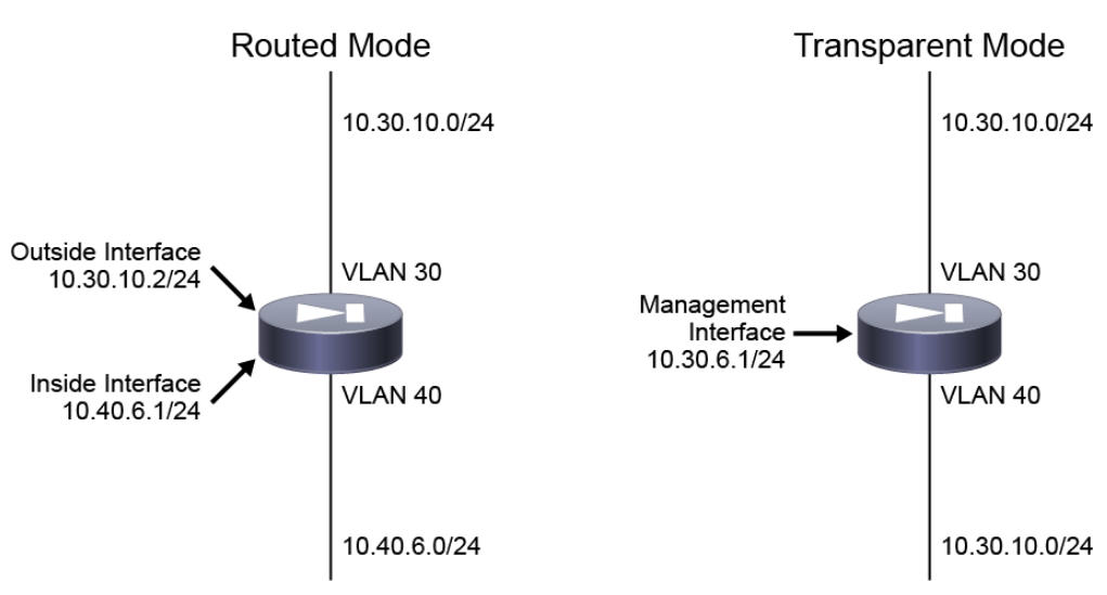
Advanced stateful firewalls, such as the Cisco ASA, can also be deployed in the network in one of two ways: routed mode or transparent mode.
A firewall in routed mode, connects to different networks on its inside and outside interfaces, and inspects and routes packets between the inside and outside networks. As shown in the figure below, the routed firewall inside interface is on the 10.40.6.0/24 subnet and the outside interface is on the 10.30.10.0/24 subnet.
A firewall in transparent mode, on the other hand, connects to the same network on its inside and outside interfaces. Because the transparent firewall is not a routed hop, it can be integrated into an existing network more easily (for example, no need to make any IP addressing changes on the inside or outside hosts). A transparent firewall is considered a layer 2 “bump in the wire” firewall with no routing ability. As shown in the figure below, the transparent firewall inside and outside interfaces are on the same 10.30.10.0/24 subnet.
Network Taps
Security analysts monitor system logs and data from security appliances to monitor the network and look for any suspicious activity. Sometimes, the security analyst uses packet captures on certain links in the network to perform a detailed analysis or troubleshoot issues that are related to heavy bandwidth usage or suspicious activity. Network taps are simple devices that play an important role in that they allow security analysts to capture traffic on an already overloaded or congested link between two network devices.
The network tap is installed between two network devices (for example, a switch and a workstation) where it provides one or more ports that output the traffic that is going between the devices. The security analyst should have a basic understanding of network tap benefits, limitations, and operation. A typical fiber-based network tap is depicted in the diagram below.
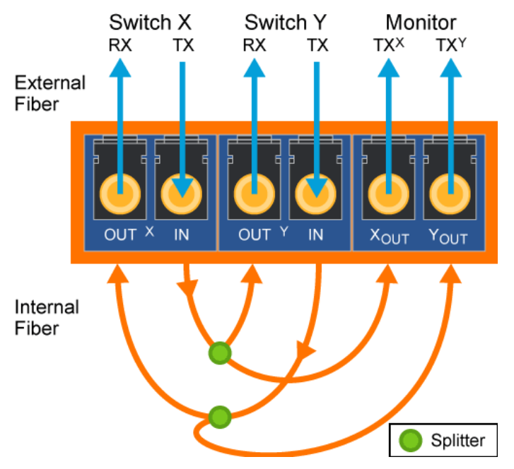
Network taps are passive hardware devices that must physically be inserted between two communicating network devices to operate. Installation of the network tap requires a brief interruption of the link onto which it is installed, likely resulting in downtime. Taps are often rack-mounted, which can lead to space considerations in some networking environments. As the requirement to monitor more connections increases, multiple taps (or more expensive multiconnection taps) may become necessary. The costs of network taps can vary from relatively inexpensive versions for ethernet costing around $100, to more expensive options designed to monitor optical connections costing $1000 or more. Finally, keep in mind if the capture device is expected to monitor both sides of a connection, two network interfaces are necessary per tap. With large monitoring requirements, the cost of network taps can quickly become prohibitive.
Remember that network taps operate at the physical layer and must be physically inserted in the link between two network devices. As such, taps are physical-layer devices not capable of processing or altering traffic between hosts, nor is the tap able to filter traffic being sent to the capture device. Instead, network taps provide a means to monitor conversations between two sides of a connection, passively enabling packet capture and real-time analysis. Because modern-day physical layer transmission technologies are full-duplex, network taps monitor the transmit (Tx) pins of each device. This setup offers two distinct advantages in that it allows the capture device to differentiate the two sides of the connection and it ensures that the tap itself does not introduce congestion or degrade performance across the link. Lastly, since receive and transmit pins are separated, collisions caused by insertion of the tap onto the link are not possible.
The following figure provides an example of a typical network tap installation between a gateway router and Internet perimeter firewall.
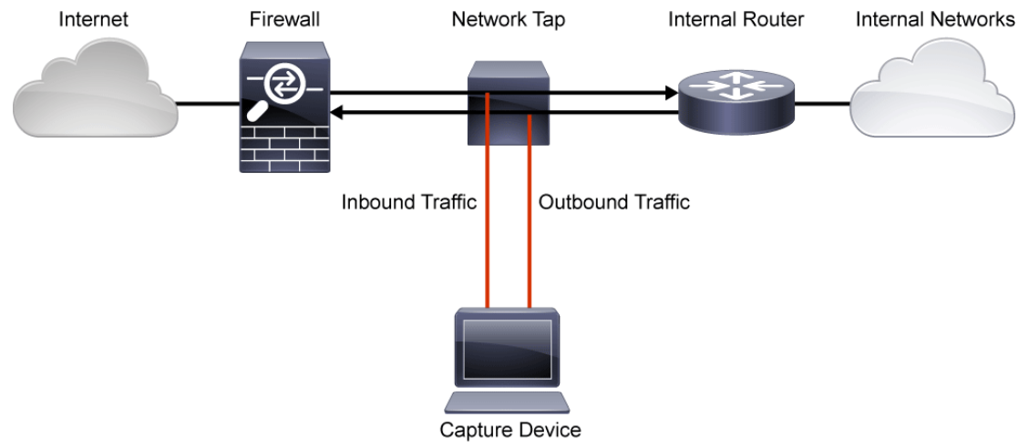
In this example, a network tap is inserted between a perimeter firewall and the primary router of the network. Installing a tap at this network location enables administrators to monitor all traffic as it enters or exits the network. The capture device that is attached to the tap could serve one or more functions. For example, the device could capture traffic from specific addresses or ports, rotate captures of all traffic, or incorporate real-time analysis as part of an IDS. There is no possibility of the capture device altering the traffic across the connection between the firewall and gateway router. It would also not be possible for the capture device to generate traffic that is to be sent across the backbone.
Because network taps work at the speed of the link, network performance is not impacted or degraded by monitoring the connection. Remember that network taps are passive devices, often built to fail-safe. Fail-safe means that if hardware fails or power is lost, the connection between the two devices is not affected. The tap separates the Tx pins of each device, so the capture device can easily determine which side of the conversation transmitted the captured traffic.
Switched Port Analyzer
Implementing taps to monitor network communications has limitations including scalability, cost, and flexibility of deployment. Security administrators working on modern networks require a more flexible approach to capturing communications for monitoring purposes. The SPAN (Switched Port Analyzer) feature is a tool that security administrators can use to overcome many of the limitations inherent with network taps.
The SPAN feature was introduced on switches because of a fundamental difference that switches have with network hubs. When a hub receives a packet on one port, the hub sends out a copy of that packet on all ports except on the one where the hub received the packet making it relatively easy to capture communications across all devices that are attached to that network hub. Layer 2 switches operate differently than hubs. After a Layer 2 switch boots, it builds a Layer 2 forwarding table based on the source MAC addresses of the different packets the switch receives. After this forwarding table is built, the switch forwards traffic that is destined for a specific MAC address directly to the corresponding port. As a result a packet capture device connected to another port on the Layer 2 switch would be filtered from any traffic that is not specifically destined for its MAC address (except broadcast traffic, multicast traffic where Cisco Group Management Protocol or IGMP snooping is disabled, and unknown unicast traffic).
The SPAN feature reduces the expense and wiring issues that are associated with network taps. Rather than purchase and install dedicated hardware to monitor a connection between two hosts, the switch that is already forwarding traffic can be configured to mirror that traffic to another port on the same switch. This option allows the switch to take the place of a network tap, lowering cost, eliminating space requirements and the downtime that is required to install a network tap. In addition, multiple ports on a single switch can be monitored, meaning that a single switch can serve in place of multiple taps.
In the figure below, a Layer 2 switch has been configured with a local span port that mirrors all traffic from two of its ports to the port attached to a network analyzer.
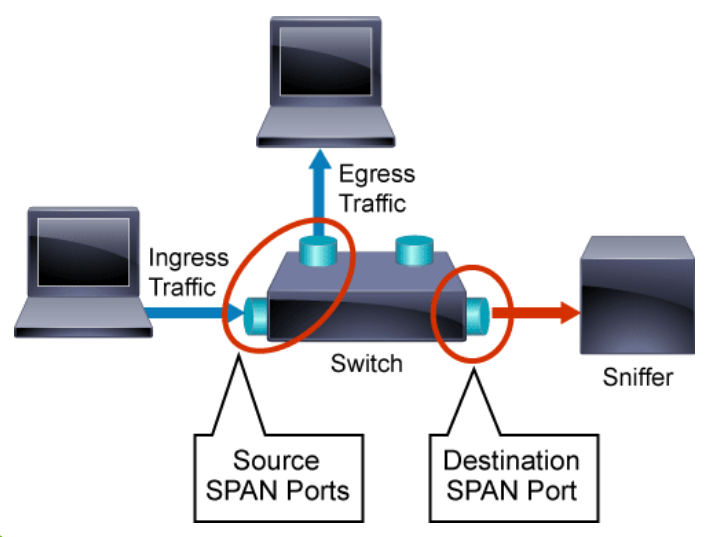
Although SPAN functionality is supported by multiple hardware vendors, each vendor may refer to SPAN and its components using slightly different terminology. While the feature is most commonly called SPAN, the terms port monitoring and port mirroring are also common.
On Cisco IOS devices, SPAN must be enabled from configuration mode. This means that the security analyst must have appropriate administrator privileges to enable the SPAN feature. Configuring SPAN involves two steps. First, the source is specified as one or more interfaces or VLANs. Second, the destination interface is specified.
It is also important to note that multiple SPAN monitoring sessions can be configured on the same switch. In the figure below, two simultaneous SPAN sessions have been enabled, mirroring traffic to two different network analyzers. In this case, the SPAN sessions have been configured to capture all traffic within a specific VLAN to the destination SPAN port.
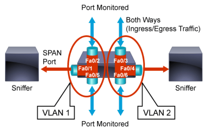
Different Cisco devices may have different SPAN capabilities and configuration details specific to that individual device and the types of ports that can be used when implementing SPAN. It is important that network administrators and security analysts understand the proper use and configuration of the SPAN feature for the devices on which SPAN is deployed. For example, different switches or even the same type of switches running different versions of Cisco IOS may have different limitations on the number of simultaneous SPAN sessions that can be configured.
The use of SPAN provides many benefits to the security analyst. Because existing hardware is used to enable the SPAN feature, SPAN is both cost-effective and easy to deploy. Enabling the SPAN feature, unlike network taps, requires no downtime. Further, multiple sources can be configured as SPAN source ports to a single destination SPAN port allowing the security analyst to capture traffic from multiple devices at one time. Minimal filtering is available when configuring SPAN by specifying sources on a per-interface, per-VLAN, or directional (ingress, egress, or both) criteria.
The SPAN feature is an excellent tool for troubleshooting and for specific packet capture activities. It is critical to note that except for carefully planned topologies, SPAN consumes too many switch and network resources to enable permanently. Security analysts should exercise all possible care when enabling and configuring SPAN. The traffic that SPAN copies can impose a significant load on the switch and the network. To minimize the load, configure SPAN to copy only the specific traffic that you want to analyze. Select SPAN sources that carry as little unwanted traffic as possible. For example, a port as a SPAN source might carry less unwanted traffic than a VLAN.

Before enabling SPAN, carefully evaluate the SPAN source traffic rates, and consider the performance implications and possible oversubscription points including SPAN destination, Fabric channel, and the forwarding engine (PFC/DFC). To avoid disrupting traffic, do not oversubscribe any of these points in your SPAN topology.
Some oversubscription and performance considerations to note are:
- SPAN doubles traffic internally.
- SPAN adds to the traffic being processed by the switch fabric.
- SPAN doubles forwarding engine load.
- The supervisor engine handles the entire load that is imposed by egress SPAN (also called transmit SPAN).
The destination for each monitor session command can become a bottleneck when the source has more bandwidth than the destination. Mirrored traffic could then be delayed or dropped. Furthermore, SPAN functionality is reserved for feature-filled, managed switches and routers, with limitations on the number of sessions, depending on vendor, platform, and version. The capture device must be directly connected to a port on the local device, which can become a limiting factor in large organizations. Finally, the number of SPAN ports that are configurable on a given device is limited, based on the hardware design.
Remote Switched Port Analyzer
Situations can arise requiring packet capture from remote locations of the network or potentially across multiple locations within the enterprise LAN at the same time. These situations make it difficult if not impossible to utilize SPAN functionality, as span requires the destination SPAN port to be locally attached. RSPAN, allows the security administrator to monitor source ports that are spread across a switched network. The RSPAN functions the same as SPAN monitoring. The traffic that is monitored by RSPAN is not directly copied to the destination port as with SPAN, but instead flooded into a special RSPAN VLAN. The destination port can then be located anywhere in the network on the RSPAN VLAN. When using RSPAN, several destination ports can be defined.
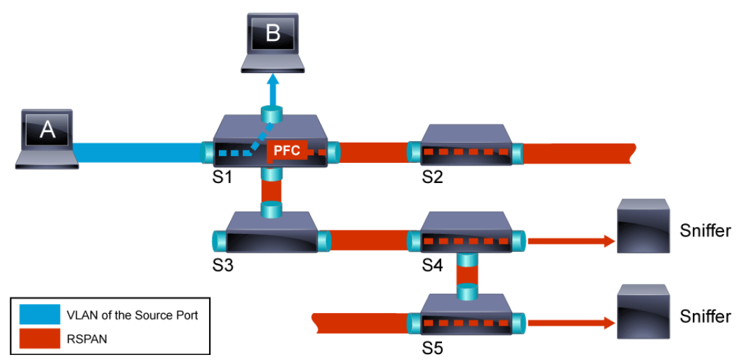
In the figure above, RSPAN is configured to monitor traffic that is sent by host A. When host A generates a frame that is destined for host B, the packet is copied into a predefined RSPAN VLAN. From there, the packet is flooded to all other ports that belong to the RSPAN VLAN. All the interswitch links that are shown in the figure are configured as trunk ports, which is a requirement for RSPAN. The only access ports in the network are the destination ports, where hosts are connected or where the sniffers are connected (switches S4 and S5).
On Cisco IOS devices, remote SPAN must be enabled from configuration mode. This means that the security analyst must have appropriate administrator privileges to enable the RSPAN feature. Configuring remote SPAN is similar to configuring SPAN. The key difference is that the destination SPAN port in the source switch is actually an RSPAN VLAN. On the remote destination switch, the remote switch where the traffic will be directed, the source SPAN port is the RSPAN VLAN, and its destination is the single SPAN port that is attached to the network analyzer.
When configuring RSPAN, keep in mind that Packets only enter the RSPAN VLAN in switches that are configured as the RSPAN source. Currently, a switch can only be the source for one RSPAN session, meaning a source switch can only feed one RSPAN VLAN at a time. Further, all switches must be connected together with interswitch trunk ports connecting them. Trunks (802.1Q or ISL) are required as they transport VLANs across the network and therefore RSPAN cannot cross any layer 3 boundaries. On intermediate switches not on the path to the destination, VLAN pruning can eliminate unwanted RSPAN traffic from transiting these trunk ports.

One other important note is the RSPAN VLAN is carried across the LAN over trunk ports. In order to prevent bridge loops, the STP has been maintained on the RSPAN VLAN. Therefore, RSPAN cannot monitor BPDUs (Bridge Protocol Data Unit).
Different Cisco devices may have different RSPAN capabilities and configuration details specific to that individual device and the types of ports that can be used when implementing RSPAN. It is important that network administrators and security analysts understand the proper use and configuration of the RSPAN feature for the devices on which RSPAN is deployed. For example, different switches or even the same type of switches running different versions of IOS may have different limitations on the number of simultaneous RSPAN destinations that can be configured.
RSPAN combines the functionality of SPAN with the flexibility of VLANs. The functionality of per-interface, per-VLAN, and directional filtering is still supported without the need to bring down a link. Introducing VLAN support allows for enterprise-wide port monitoring with the capture device able to reside at a centralized location.
The use of remote SPAN provides many benefits to the security analyst. Because existing hardware is used to enable the RSPAN feature, RSPAN is both cost-effective and fairly easy to deploy. Enabling the RSPAN feature or changing its configuration, unlike network taps, requires no downtime. Further, multiple sources can be configured as RSPAN source ports to a single destination RSPAN port allowing the security analyst to capture traffic from multiple devices at one time. Minimal filtering is available when configuring RSPAN by specifying sources on a per-interface, per-VLAN, or directional (ingress, egress, or both) criteria.
Unfortunately, RSPAN increases the likelihood of network performance degradation. Recall that SPAN introduced potential performance considerations. RSPAN adds to those by broadcasting SPAN traffic across the entire network on the RSPAN VLAN. Bottlenecks can quickly limit the throughput of multiple monitored connections being pushed across several hops. In addition, RSPAN must be supported on the endpoints, and trunk ports must connect all switches in the RSPAN domain as VLAN headers must be preserved on all hops between the endpoints.
Intrusion Prevention System
Intrusion sensors are systems that detect activity that can compromise the confidentiality, integrity, and availability of information resources, processing, or systems. Intrusions can come in many forms. The security analyst investigates various alerts from intrusion sensors and security appliances to determine if an alert is indicating malicious activity, a false positive, or to recommend where tuning of the intrusion sensor may be required.
To detect intrusions, various technologies have been developed. The first technology that was developed, IDS, had sensing capabilities but little capability to take action upon what it detected. An IPS builds upon previous IDS technology. An IPS has the ability to analyze traffic from the data link layer to the application layer. For example, an IPS can:
- Analyze the traffic that controls Layer 2 to Layer 3 mappings, such as ARP and DHCP.
- Verify that the rules of networking protocols such as IP, TCP, UDP, and ICMP are followed.
- Analyze the payload of application traffic to identify things such as network attacks, the presence of malware, and server misconfigurations.
IPS can identify, stop, and block attacks that would normally pass through a traditional firewall device. When traffic comes in through an interface on an IPS, if that traffic matches an IPS signature/rule, then that traffic can be dropped by the IPS. The essential difference between an IDS and an IPS is that an IPS can respond immediately, and prevent possible malicious traffic from passing. An IDS simply produces alerts when suspicious traffic is seen. An IDS is not responsible for mitigating the threat.
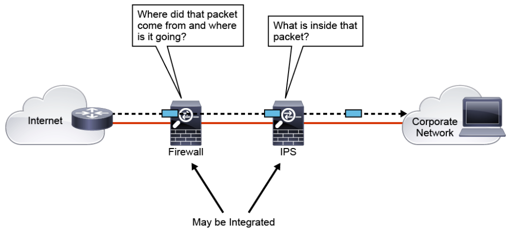
The figure above shows a common IPS deployment, in which the Cisco adaptive security appliance (Cisco ASA) controls access between the corporate network and the Internet, based on source and destination IP addresses and ports, while the IPS controls access based on packet payload. An IPS also has other valuable capabilities, such as providing deeper insight into what is actually happening on your network.
IPS technology is deployed in a sensor, which is variously described as one of the following:
- An appliance that is specifically designed to provide dedicated IPS services
- A module that is installed in another network device, such as an adaptive security appliance, a switch, or a router
Intrusion detection technology uses different strategies to detect and mitigate against attacks:
- Anomaly detection: This type of technology generally learns patterns of normal network activity and, over time, produces a baseline profile for a given network. Sensors detect suspicious activity by evaluating patterns of activity that deviate from this baseline.
- Rule-based detection: Attackers use various techniques to invade and compromise systems. Many techniques are directed at known weaknesses in operating systems, applications, or protocols. Various remote surveillance techniques are also frequently used. Some surveillance and attack methods have known patterns by which the method can be identified. Malicious activity detectors typically analyze live network traffic using a database of IPS rules (or also called IPS signatures) to determine whether suspicious activity is occurring.
- Reputation-based: IPS security appliances can also make informed decisions on whether to permit or block the traffic based on reputations. Reputation-based filtering allows the IPS to block all traffic from known bad sources before any significant inspection is done.
