Cisco CCNA Cyber Ops SECFND 210-250, Section 1: Understanding the TCP/IP Protocol Suite
1.2 OSI Model
1.3 TCP/IP Model
1.4 Introduction to the Internet Protocol
1.5 IP Addressing
1.6 IP Address Classes
1.7 Reserved IP Addresses
1.8 Public and Private IP Addresses
1.9 IPv6 Addresses
1.10 Introduction to the Transmission Control Protocol
1.11 TCP Three-Way Handshake
1.12 Introduction to the User Datagram Protocol
1.13 TCP and UDP Ports
1.14 Address Resolution Protocol
1.15 Host-to-Host Packet Delivery Using TCP
1.16 Dynamic Host Configuration Protocol
1.17 Domain Name System
1.18 Internet Control Message Protocol
1.19 Packet Capture Using tcpdump
1.20 Wireshark
The OSI Model (Open Systems Interconnection Reference Model)
The OSI reference model separates network functions into seven categories, or layers, and defines the network functions that occur at each layer. Each layer provides services to the layer above it, uses services from the layer below it, and has an abstract connection to the same layer on the peer system. This modularization of function simplifies the implementation of complex network functions. And by defining these functions, the OSI model helps users understand how data from an application program travels through a network medium to an application program that is located in another computer.
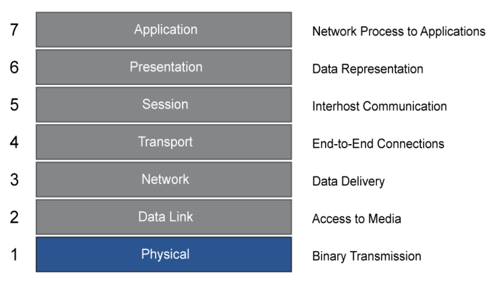 The layers of the OSI model are as follows:
- Layer 1, Physical: The physical layer defines the electrical, mechanical, procedural, and functional specifications for activating, maintaining, and deactivating the physical link between end systems. Characteristics such as voltage levels, timing of voltage changes, physical data rates, maximum transmission distances, physical connectors, and other similar attributes are defined by physical layer specifications. Examples of Layer 1 devices are transceivers, modems, CSU/DSU, and hubs.
- Layer 2, Data Link: The data link layer defines how data is formatted for transmission and how data accesses the physical layer. This layer also typically includes error checking. Examples of Layer 2 devices are bridges and switches, which forward and flood traffic based on MAC addresses. Although MAC addresses are typically physical addresses, they operate at the data link layer of the OSI model.
- Layer 3, Network: The network layer provides connectivity between two host systems that can be located on geographically separated networks. It provides logical addressing, selects the best path for data delivery, and routes data packets. An example of a Layer 3 device is a router.
- Layer 4, Transport: The transport layer segments data from the system of the sending host and reassembles the data into a data stream on the system of the receiving host. For example, business users in large corporations often transfer large files from field locations to a corporate site. Reliable delivery of the files is important, so the transport layer breaks down large files into smaller pieces, which are known as segments, that are less likely to incur transmission problems.
The boundary between the transport layer and the session layer can be thought of as the boundary between application protocols and data-flow protocols. Whereas the application, presentation, and session layers are concerned with application issues, the lower four layers are concerned with data transport issues.
The transport layer shields the upper layers from transport implementation details. Specifically, issues such as reliability of transport between two hosts are assigned to the transport layer. In providing a communication service, the transport layer establishes, maintains, and properly terminates virtual circuits. Transport error detection, error recovery, and information flow control ensure reliable service. - Layer 5, Session: The session layer establishes, manages, and terminates sessions between two communicating hosts. The session layer also synchronizes dialog between the presentation layers of the two hosts and manages their data exchange. For example, web servers have many users, so there are many communication processes open at a given time. Therefore, it is important to keep track of which user communicates on which path.
- Layer 6, Presentation: The presentation layer ensures that the information that is sent at the application layer of one system is readable by the application layer of another system. For example, a PC program communicates with another computer, with one computer using EBCDIC and the other using ASCII to represent the same characters. If necessary, the presentation layer translates between multiple data formats by using a common format.
- Layer 7, Application: The application layer is the OSI layer that is closest to the user. This layer provides network services to the applications of the user, such as email, file transfer, and terminal emulation. The application layer differs from the other layers in that it does not provide services to any other OSI layer, but only to applications outside the OSI model. The application layer establishes the availability of intended communication partners and synchronizes and establishes agreement on procedures for error recovery and control of data integrity
Data Encapsulation and De-Encapsulation
Information that is to be transmitted over a network must undergo a process of conversion at both the sending end and the receiving end of the communication. That conversion process is known as encapsulation and de-encapsulation.
The information that is sent on a network is referred to as data or data packets. If one computer wants to send data to another computer, the data must first be packaged by a process called encapsulation. Encapsulation works very similarly to sending a package through a postal service. The first step is to put the contents of the package into a container. Next, you write the address of the location to which you want to send the package on the outside of the container. Then you put the addressed package into the postal service collection bin, and the package begins its route toward its destination.
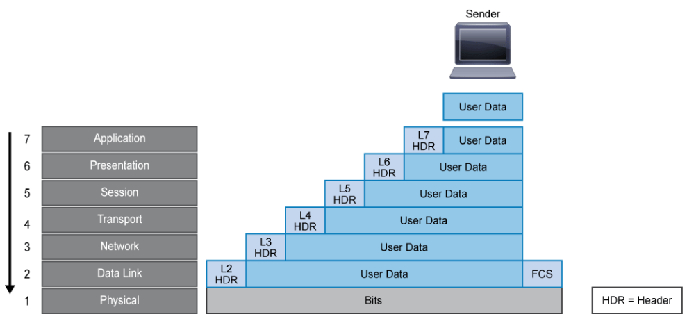
Encapsulation wraps data with each network layer’s necessary protocol information before network transit. As the data moves down through the layers of the OSI reference model, each OSI layer adds a header (and a trailer, if applicable) to the data before passing it down to a lower layer. The process is illustrated in the figure below. The headers and trailers of an upper layer are not for use by the lower layers, instead they contain control information for the network devices along the way, and ultimately, the receiver. The control information ensures proper delivery of the data and to ensure that the receiver can correctly interpret the data.
 The following steps occur to encapsulate data:
- The user data is presented to the application layer.
- The application layer adds the application layer header (Layer 7 header) to the user data. The Layer 7 header and the original user data become the data that is passed down to the presentation layer.
- The presentation layer adds the presentation layer header (Layer 6 header) to the data. The combined data and header then become the data that is passed down to the session layer.
- The session layer adds the session layer header (Layer 5 header) to the data. This combination then becomes the data that is passed down to the transport layer.
- The transport layer adds the transport layer header (Layer 4 header) to the data. This combination, which is known as a segment, becomes the data that is passed down to the network layer.
- The network layer adds the network layer header (Layer 3 header) to the data. This combination, which is known as a packet, becomes the data that is passed down to the data link layer.
- The data link layer adds the data link layer header and trailer (Layer 2 header and trailer) to the data. A Layer 2 trailer is usually the FCS (Frame Check Sequence. Extra characters added to a frame for error control purposes.), which is used by the receiver to detect whether the data is in error. This combination, which is known as a frame, then becomes the data that is passed down to the physical layer.
- The physical layer then transmits the bits onto the network media.
Note:
The format of the data at each layer is generically known as the PDU. There is also terminology that is used for the PDU (Protocol Data Unit) at certain layers. For example, the Layer 2 (data link layer) PDU is called a "frame." The Layer 3 (network layer) PDU is called a "packet." The Layer 4 (transport layer) PDU is called a "segment" for TCP or a "datagram" for UDP.
When the remote device receives a sequence of bits, the physical layer at the remote device passes the bits to the data link layer for manipulation, beginning the de-encapsulation process. The de-encapsulation process is similar to that of reading the address on a package to see if it is for you, and then removing the contents of the package if it is addressed to you.
Note:
The term "decapsulation" is sometimes used in place of the term "de-encapsulation." Both terms are acceptable.
When the data link layer receives the data, it checks the data-link trailer (the FCS) to see if the binary data has been corrupted in transit. While some data-link technologies can request retransmission for corrupt data, most modern data-links, including Ethernet, will simply discard the corrupted frame. In such environments, if reliability is required, it must be provided by upper layers in the stack. If the data is not in error, the data link layer reads and interprets the control information in the data-link header. The data link layer strips the data-link header and trailer, and then passes the remaining data up to the network layer based on the control information in the data-link header. Each subsequent layer performs a similar de-encapsulation process eventually presenting the original user data from the source to the program running on the peer system.
TCP/IP Model
Development of the 4-layer TCP/IP model started before work began on the 7-layer OSI model. As it turned out, TCP/IP had too much momentum to be overtaken by the OSI model or any of the other competing network models. The TCP/IP model is now the dominant protocol suite that is used on today’s Internet. The TCP/IP model is also referred to as the TCP/IP protocol suite, the Internet protocol suite, the TCP/IP stack, and the DoD model.
Development of the OSI model began in the late 1970s, and the model was published in 1984. Although the OSI model was never actually implemented, the theory that it embodies has influenced the continual development and maturation of TCP/IP. TCP/IP was developed in a rather ad hoc fashion. The timeline includes the following:
- ARPANET, the precursor to the Internet, was developed in the late 1960s.
- In May of 1974, Kahn and Cerf published a paper titled “A Protocol for Packet Network Intercommunication,” which described the early ideas of what would become the TCP/IP model.
- In March of 1982, the US Department of Defense declared TCP/IP as the standard for all military computer networking.
- On January 1, 1983 (known as "Flag Day"), the ARPANET switched from the old networking protocol, NCP, to TCP/IP.
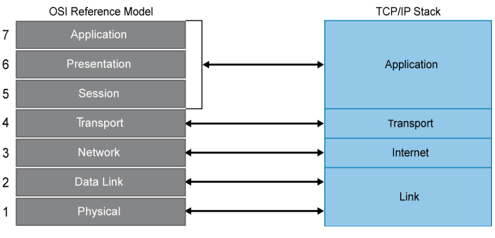
TCP/IP includes not only TCP and IP, but also specifications for other protocols, such as UDP, ICMP, and so on. It also includes common applications such as electronic mail, terminal emulation, and file transfer. TCP/IP embodies every aspect of modern network communications that use IP at the network layer. TCP operates at the transport layer of the OSI and TCP/IP models and is responsible for making sure that the data that the source device sends arrives at its destination. IP operates at the network layer of the OSI model (Internet layer of the TCP/IP model) and is responsible for the transmission of data. It does not do any error correction itself. The figure below provides a comparison of the OSI and TCP/IP models.
 In the late 1970s through the 1980s, no networking protocol was dominant. There were many, including IBM SNA, DEC DECnet, Apple AppleTalk, Banyan Vines, and Novell IPX. Due to many historical circumstances and compared to all the competitors, TCP/IP has gained momentum, and has become the de facto standard in the industry.
Take a closer look at the four layers of the TCP/IP model:
- Link layer: This layer is also known as the network access layer and is the equivalent of both the physical and data link layers of the OSI model. It deals with components such as cables, connectors, and network cards, like OSI Layer 1. Like Layer 2 of the OSI model, the link layer of the TCP/IP model is concerned with hardware addresses.
- Internet layer: This layer aligns directly with Layer 3 of the OSI model. You may also know this layer as the network layer. It routes data from the source to the destination by defining the packet and the addressing scheme, moving data between the link and transport layers, routing packets of data to remote hosts, and performing fragmentation and reassembly of data packets. The Internet layer is where IP operates.
- Transport layer: This layer is directly aligned with Layer 4 of the OSI model: It is the core of the TCP/IP architecture. It is the layer where TCP and UDP operate. This layer provides communication services directly to the application processes that are running on network hosts.
- Application layer: This layer corresponds to Layers 5, 6, and 7 of the OSI model. It provides applications for file transfer, network troubleshooting, and Internet activities. It also supports network APIs, which allow programs that have been created for a particular operating system to access the network.
Variants of both the TCP/IP model and IP itself have been developed. IPv4 was the basis of the DoD standard in 1982. Later IPv6 was developed to deal with many of the shortcomings of IPv4. The industry is currently working through a long transition period between IPv4 and IPv6.
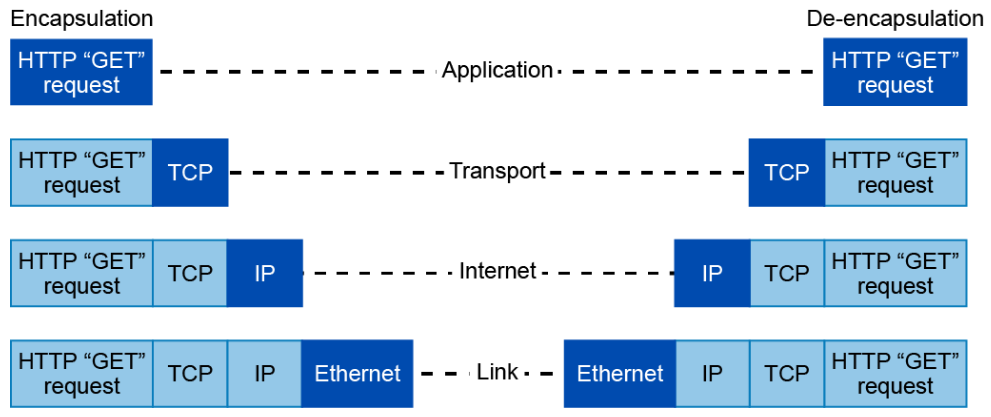
The example in the figure below illustrates encapsulation and de-encapsulation in light of the TCP/IP model. It shows what happens when you use a web browser to go to a site on the Internet.
Your web browser is an application that operates at the application layer. After you enter an address in the address bar, the browser passes data (an HTTP “GET” request) to the application layer. When the application layer passes the data to the transport layer, the transport layer may split the data into segments (if the amount of data is deemed large enough). The transport layer adds a TCP header to the segment, encapsulating it in TCP. If there are multiple segments, TCP sequences them so the data stream can be reassembled when it reaches its destination. The segment is then passed to the Internet layer, where it receives an IP header to encapsulate it as an IP packet. The IP header contains source and destination IP addresses, which will enable the data to be properly routed to the destination. The Internet layer may also break a large packet into smaller fragments, then the fragments are reassembled at the Internet layer at the destination system. When the IP packet reaches the link layer, it is encapsulated in an Ethernet frame, which contains source and destination hardware, or MAC, addresses. The frame is then transmitted in the form of bits onto the physical network.
 At the destination, the process is reversed. As information in each header is read, the header is stripped and the remaining data is sent up to the next layer.
Introduction to the Internet Protocol
The IP layer in TCP/IP determines where packets of data are to be routed based on their destination IP addresses. IP uses packets to carry information through the network. A packet is a self-contained, independent entity that contains data and sufficient information to be routed from the source to the destination without reliance on previous packets.
IP has these characteristics:
- IP operates at Layer 3 of the OSI model (network layer), and Layer 2 of the TCP/IP stack (Internet layer).
- IP is a connectionless protocol in which a one-way datagram is sent to the destination without advance notification to the destination device. The destination device receives the data and does not return any status information to the sending device.
- IP uses hierarchical addressing in which the network ID resembles a street and the host ID resembles a house or office building on that street.
- IP provides service on a best-effort basis and does not guarantee packet delivery. A packet can be misdirected, duplicated, or lost on the way to its destination.
IP does not provide any special features that recover corrupted packets. If these services are required, they must be provided by higher layers in the protocol stack.
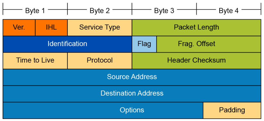 Attackers may manipulate the fields in the IP header to carry out their attacks, so it is important for an analyst to understand the different fields of the IP headers. The IPv4 header fields are:
- Version: A 4-bit field that identifies the IP version being used. Version is 4 referred to as IPv4.
- IP Header length: A 4-bit field containing the length of the IP header. The minimum length of an IP header is 20 bytes
- Type of service: The 8-bit ToS field traditionally uses 3 bits for IP Precedence. The newer redefinition of the ToS field uses a 6-bit DSCP (Differentiated Services Code point) field and a 2-bit ECN (Explicit Congestion Notification) field to identify the level of service a packet receives in the network.
- Total length: Specifies the length of the IP packet that includes the IP header and the user data. The length field is 2 bytes, so the maximum size of an IP packet is 65,535 bytes.
- Identifier, flags, and fragment offset: As an IP packet moves through the Internet, it might need to cross a route that cannot handle the size of the packet. The packet will be divided, or fragmented, into smaller packets and reassembled later. These fields are used to fragment and reassemble packets.
- Time to live: It is possible for an IP packet to roam aimlessly around the Internet. If there is a routing problem or a routing loop, then you don't want packets to be forwarded forever. A routing loop is when a packet is continually routed through the same routers over and over. The TTL field is initially set to a number and decremented by every router that is passed through. When TTL reaches 0, the packet is discarded.
- Protocol: In the layered protocol model, the layer that determines which application the data is from or which application the data is for is indicated using the Protocol field. This field does not identify the application, but identifies a protocol that sits above the IP layer that is used for application identification. For example, protocol number 1 = ICMP, 6 = TCP, 17 = UDP.
- Header checksum: A value that is calculated based on the contents of the IP header. Used to determine if any errors have been introduced during transmission.
- Source IP address: 32-bit IP address of the sender.
- Destination IP address: 32-bit IP address of the intended recipient.
- Options and padding: A field that varies in length from 0 to a multiple of 32 bits. If the option values are not a multiple of 32 bits, 0s are added or padded to ensure that this field contains a multiple of 32 bits.
IP Addressing
Consider how physical street addresses are necessary to locate specific homes and businesses, so that mail can reach those real-world locations efficiently. In a similar way, logical IP addresses are used to identify the location of specific devices on an IP network so that data can reach those network locations efficiently. Every host, computer, networking device, or peripheral connected to the Internet must have an IP address. Without a structure for allocating all those IP addresses, it would be impossible to route packets efficiently.
The IPv4 address is the most common type of address that is currently used on the Internet. An IPv4 addresses is a 32-bit number that describes the location of a network device.
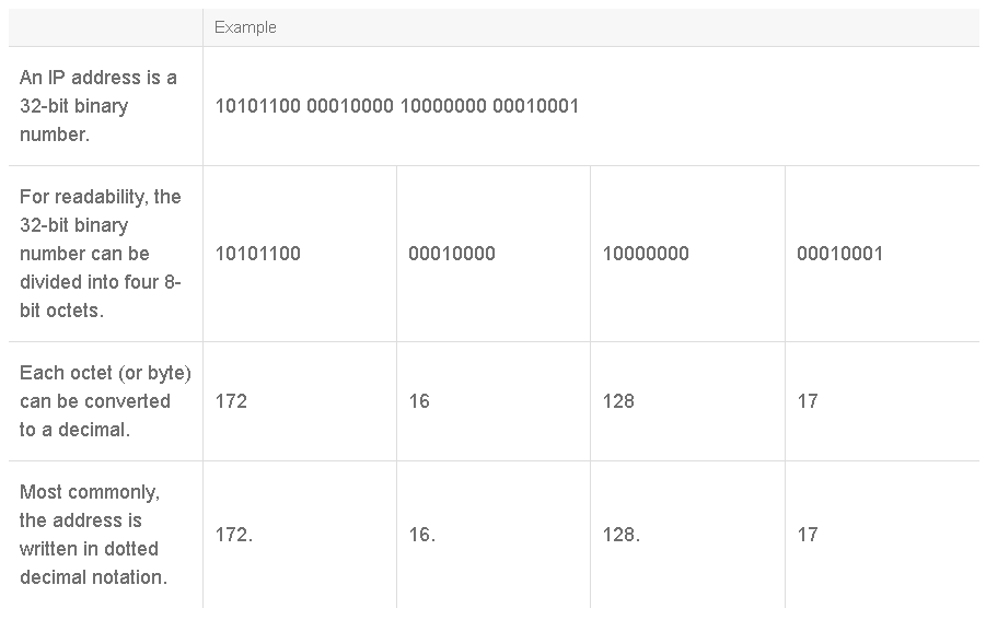
In the decimal representation of an IP address, the value of each octet can range from 0 to 255. The octets are separated by a period, or dot. This scheme is known as dotted decimal notation. The IP address that is shown in the table can be written as 172.16.128.17 and spoken as “172 dot 16 dot 128 dot 17.”
An IP address is a hierarchical address and consists of two parts, the network ID and the host ID. The network ID (network address portion) identifies the network of which an IP address is a part. It starts from the leftmost bits and extends to the right. The host ID (the host address portion) uniquely identifies a host, or endpoint, on a network. These endpoints are the servers, computers, and other devices that are connected to the network. The host ID starts from the right-most bits and extends to the left. Many computers can share the same network ID, but combining the network ID with a host ID in an IP address uniquely identifies a device on the network. For example, in the figure below, hosts 192.168.1.2, 192.168.1.3, and 192.168.1.4 share the network ID 192.168.1.0, but they have their own unique host IDs, .2, .3, and .4, respectively.
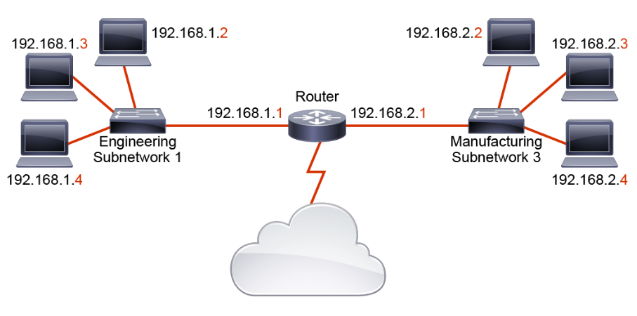
Hosts that share the same network ID are said to be on the same network. Most hosts on a network can directly communicate only with devices on the same network. If the hosts need to communicate with devices that have interfaces that are assigned with other network IDs, there needs to be a network device that can route data between the networks. Routers can route data between networks because they maintain information about routes to the various networks. A network ID enables a router to put a packet onto the appropriate network.
Networks have their own IP addresses. These addresses have binary 0s in all host bit positions. In the figure, a router sits between two different networks, the 192.168.1.0 network and the 192.168.2.0 network. Hosts on the 192.168.1.0 network can communicate directly with each other, but any packets they send to hosts on the 192.168.2.0 network must be sent through the router. Also notice that host 192.168.1.2 and host 192.168.2.2 have the same host ID. Although it is possible for two devices on different networks to have the same host ID, each host on the same network must have a unique host ID.
IP Address Masks
For IPv4, a subnet mask is a 32-bit combination that identifies which part of the address is the network portion and which part is the host portion. It performs this function by using 1s and 0s. A subnet mask is created by placing a binary 1 in each bit position that represents the network portion and placing a binary 0 in each bit position that represents the host portion. For example, a subnet mask of 255.255.255.0 (11111111.11111111.11111111.00000000) applied to the IP address 192.168.7.5 specifies that the binary digits of the first three octets are the network portion of the address and every bit of the last octet specifies the host address. Hence, 192.168.7.0 is the network address and .5 is the host address. A subnet mask helps routers determine the network path for packets. The figure below provides another example.
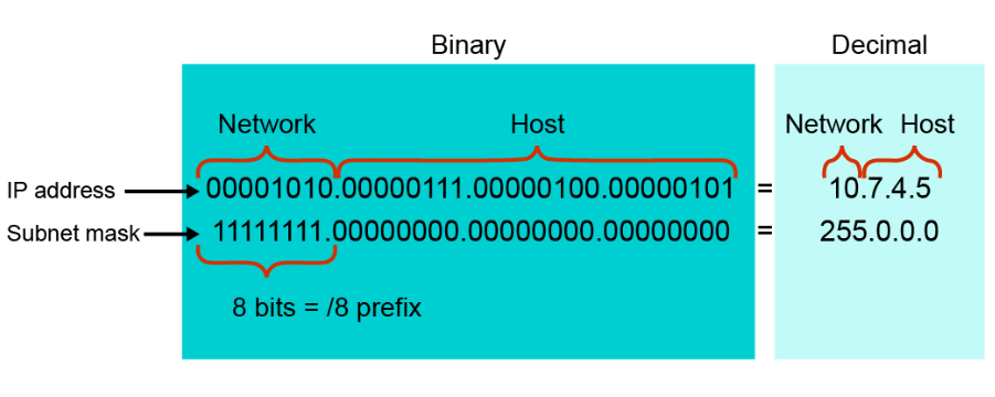
When you express an IP address, you accompany it with a subnet mask in dotted decimal format, or you append a prefix length. A prefix length performs the same function as a subnet mask by providing the number of bits in the address that are used for the network portion. For example, in 172.16.55.87/20, /20 is the prefix length. It tells you that the first 20 bits are the network address. The remaining 12 bits make up the host portion. A /20 prefix is the equivalent of the subnet mask 255.255.240.0 (11111111.11111111.11110000.00000000).
IP Address Classes
To accommodate different sizes of networks and to aid in classifying them, IP addresses are divided into categories that are called classes. Assigning IP addresses to classes is known as classful addressing. The classes were determined by the IANA (Internet Assigned Numbers Authority).
As mentioned before, each IP address consists of a network ID and a host ID. Each address class uses a fixed number of octets (that is, a fixed set of bits) to indicate the network ID. The remaining octets of the 32-bit IP address are used for host addresses. A bit or bit sequence at the start of a classful IP address determines the class of the address. This starting bit or bit sequence is known as the MSB (Most Significant Bit).
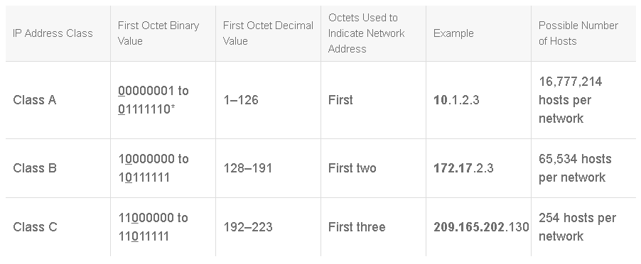
The table below shows three of the five IP address classes.
- Class A: The first 0 of a Class A address is always in the first bit (MSB) position. Because the first bit is a 0, the lowest number that can be represented is 00000000 (decimal 0), and the highest number that can be represented is 01111111 (decimal 127). However, these 2 network numbers, 0 and 127, are reserved and cannot be used as network addresses. An address that has a value in the range of 1 to 126 in the first octet of the 32-bit number is a Class A address.
- Class B: The first 0 of a Class B address is always in the second bit position. Starting the first octet with binary 10 ensures that the Class B space is separated from the upper levels of the Class A space. The remaining 6 bits in the first octet can be populated with either 1s or 0s. Therefore, the lowest number that can be represented with a Class B address is 10000000 (decimal 128), and the highest number that can be represented is 10111111 (decimal 191). An address that has a value in the range of 128 to 191 in the first octet is a Class B address.
- Class C: The first 0 of a Class C address is always in the third bit position. Therefore, the lowest number that can be represented is 11000000 (decimal 192), and the highest number that can be represented is 11011111 (decimal 223). If an address contains a number in the range of 192 to 223 in the first octet, it is a Class C address.
Note: 127 (01111111) is a Class A address reserved for local loopback interfaces and cannot be assigned to a network.
Each address class has a default mask, but each default mask can be extended to break networks into subnetworks. The default masks (and corresponding prefixes) are:
- Class A: 255.0.0.0 or a/8
- Class B: 255.255.0.0 or a/16
- Class C: 255.255.255.0 or a/24
Reserved IP Addresses
The following IP addresses are reserved and cannot be assigned to individual devices on a network:
- Network address: An IP address that has binary 0s in all host bit positions is reserved for the network address. The network address is used to identify the network itself. For example, 172.16.0.0 is an example of a Class B network address. In this address, the first two octets are reserved for the network address; that address is never used as an address for any device that is attached to it. The last two octets contain 0s because those 16 bits are for host numbers and are used for devices that are attached to the network. An example of an IP address for a device on the 172.16.0.0 network would be 172.16.16.1. Routers use network addresses when they search their IP route tables for destination network locations.
- Directed broadcast address: To send data to all the devices on a network, a broadcast address is used. Broadcast IP addresses end with binary 1s in the entire host part of the address (the host field). Consider the network in the example 172.16.0.0, in which the last 16 bits make up the host field (or host part of the address). The broadcast that would be sent out to all devices on that network would include a destination address of 172.16.255.255. The directed broadcast is capable of being routed. However, for some versions of Cisco IOS Software, routing directed broadcasts is not the default behavior.
- Local broadcast address: If an IP device wants to communicate with all devices on the local network, it sets the destination address to all 1s (255.255.255.255) and transmits the packet. For example, hosts that do not know their network number and are asking some server for the number can use this address. The local broadcast is never routed.
- Local loopback address: A local loopback address is used to let the system send a message to itself for testing. A typical local loopback IP address is 127.0.0.1.
- Autoconfiguration IP addresses: Sometimes, neither a statically nor a dynamically configured IP address is found on startup. In such instances, hosts supporting IPv4 link-local addresses (RFC 3927) generate an address in the 169.254/16 prefix range. This address can be used only for local network connectivity and operates with many caveats, one of which is that it will not be routed. You will mostly see this address as a failure condition when a PC fails to obtain an address via DHCP.
Public and Private IP Addresses
Internet stability depends directly on the uniqueness of publicly used network addresses. Therefore, some mechanism is needed to ensure that addresses are, in fact, unique. Originally, it was the responsibility of an organization that is known as the InterNIC. IANA succeeded the InterNIC. IANA carefully manages the remaining supply of IP addresses to ensure that duplication of publicly used addresses does not occur. Such duplication would cause instability in the Internet and would compromise its capability to deliver datagrams to networks using the duplicated addresses.
To obtain a public (globally unique) IP address or a block of public IP addresses, you must contact an ISP. The ISP then contacts the upstream registry or the appropriate regional registry at one of these organizations:
- AfriNIC (African Network Information Center)
- APNIC (Asia Pacific Network Information Center)
- ARIN (American Registry for Internet Numbers)
- LACNIC (Latin American and Caribbean Network Information Center)
- RIPE NCC (Réseaux IP Européens Network Coordination Centre)
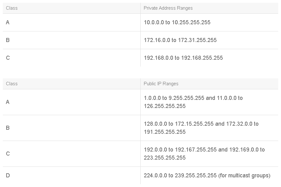
While Internet hosts require a globally unique IP address, private hosts that are not connected to the Internet can use any valid address. However, these addresses must be unique within the private network. But because many private networks exist alongside public networks, grabbing “just any address” is strongly discouraged. RFC 1918 specifies a set of IP addresses that is reserved for private networks.
These addresses are not routed on the Internet backbone. When a network using private addresses must connect to the Internet, it is necessary to translate the private addresses to public addresses. This translation process is known as NAT. A router is often the network device that performs NAT. The tables below show the private and public IP address ranges.
IPv6 Addresses
The IPv4 address space provides approximately 4.3 billion addresses. Of that address space, approximately 3.7 billion addresses are actually assignable; the other addresses are reserved for special purposes, such as multicasting, private address space, loopback testing, and research.
The IPv4 public address space has now been exhausted. Many enterprises have sufficient address space (public or private) to manage their intranet needs for the next few years. However, the length of time that is needed to transition to IPv6 demands that administrators and managers consider the issue well in advance. The largest enterprises may need to act sooner rather than later to ensure sufficient enterprise connectivity.
A simplified IPv6 header architecture and protocol operation translates into reduced operational expenses. Built-in security features mean easier security practices that are sorely lacking in many current networks. However, perhaps the most significant IPv6 improvement is the address autoconfiguration features.
The Internet is rapidly evolving from a collection of stationary devices to a fluid network of mobile devices. IPv6 allows mobile devices to quickly acquire and transition between addresses as they move among foreign networks, with no need for a foreign agent. A foreign agent is a router that can function as the point of attachment for a mobile device when it roams from its home network to a foreign network.
IPv6 address autoconfiguration also means more robust plug-and-play network connectivity. Autoconfiguration supports consumers who can have any combination of computers, printers, digital cameras, digital radios, IP phones, Internet-enabled household appliances, and robotic toys that are connected to their home networks. Many manufacturers already integrate IPv6 into their products.
The figure below compares the fields of an IPv6 header to the fields of an IPv4 header.
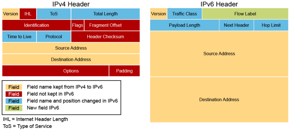
The IPv6 header fields are the following:
- Version (4-bit): Contains the value 6 rather than the value 4 contained in an IPv4 packet
- Traffic class (8 bits): This field and its functions are similar to the ToS field in IPv4.
- Flow label (20 bits): Used to tag a flow for IPv6 packets, which is new in the IPv6 protocol. The current IETF standard does not specify the details about how to manage and process the flow label.
- Payload length (16 bits): The size of the payload in octets, including any extension headers.
- Next header (8 bits): Specifies the type of the next header. This field usually specifies the transport layer protocol that is used by a packet's payload. When extension headers are present in the packet, this field indicates which extension header follows. IPv6 extension headers are optional headers that may follow the basic IPv6 header. Several types of extension headers are defined in the RFC 2460, Internet Protocol, Version 6 (IPv6) Specification.
- Hop limit (8 bits): Replaces the time to live field of IPv4. This value is decremented by one at each intermediate node visited by the packet. When the counter reaches 0, the packet is discarded.
- Source address (128 bits): The IPv6 address of the sending node.
- Destination address (128 bits): The IPv6 address of the destination node or nodes.
Extension headers, if any, follow these eight fields. The number of extension headers is not fixed, so the total length of the extension header chain is variable.
An IPv6 address is a 128-bit binary value, which can be displayed as 32 hexadecimal characters. IPv6 offers a virtually unlimited supply of IP addresses, due to its generous 128-bit address space. With IPv6, there are enough addresses to allocate more than the entire IPv4 Internet address space to everyone on the planet.
IPv6 address format:
- x:x:x:x:x:x:x:x, where x is a 16-bit hexadecimal field (case-insensitive for hexadecimal A, B, C, D, E, and F)
- Leading zeros in a field are optional
- Successive fields of zeros can be represented as :: only once per address
IPv6 address examples:
- Unicast: 2001:0000:130F:0000:0000:09C0:876A:130B or 2001:0:130f::9c0:876a:130b
- Multicast: FF01:0:0:0:0:0:0:1 or FF01::1
- Loopback: 0:0:0:0:0:0:0:1 or ::1
- Unspecified: 0:0:0:0:0:0:0:0 or ::
Introduction to the Transmission Control Protocol
TCP is a transport layer protocol that is used for sending data over an IP network. TCP provides a communication service at an intermediate level between an application program and the Internet Protocol. It is a connection-oriented protocol that provides data reliability between hosts, and it is the most widely used transport layer protocol. Each time that you browse to a site such as http://www.cisco.com, an HTTP request is encapsulated into IP packets using TCP as the transport, which are sent to the http://www.cisco.com web server to request the web page.
Since there are many TCP-based attacks, a security analyst must have a good understanding on how TCP is intended to function. For example, a common TCP attack is the SYN flood attack. In order for an analyst to understand if a server is under a SYN flood attack, the analyst needs to understand the various flags in a TCP header and how a TCP connection is established.
Using the TCP protocol services is analogous to sending certified mail through a postal service. Suppose that you live in San Francisco and you want to send a book-sized document to New York. You print the document and discover that all the pages will not fit into one envelope, so you separate the pages into groups and put each group in a separate envelope. You then tag each envelope with a sequence number so the receiver will know how to reassemble the book. You address the envelopes and send the first one as certified mail. The postal service delivers the first envelope by any truck and any route. Because it is certified, upon delivery the carrier must get a signature from the recipient and return that certificate of delivery to you. If you don’t receive that confirmation within an acceptable amount of time, you can reprint and resend those pages.
Sending each group separately is tedious, so you send several envelopes together. The postal service again delivers each envelope by any truck and any route. The recipient signs a separate receipt for each envelope in the batch as the envelopes are received. If one envelope is lost in transit, you do not receive a certificate of delivery for that numbered envelope, and you can resend all the pages of the group. Likewise, if one of the envelopes is damaged by water, the recipient can let you know the sequence number and you can reprint and resend the pages that were in the damaged envelope. After receiving all the envelopes, the recipient reassembles the pages in the correct order.
TCP has many unique characteristics that are related to how it accomplishes data transmission. The following are some characteristics of TCP:
- TCP operates at Layer 4 (the transport layer) of the OSI model.
- TCP = IP protocol number 6.
- TCP provides a service to the applications: access to the network layer.
- TCP is a connection-oriented protocol in which two network devices set up a connection to exchange data. The end systems synchronize with each other to manage packet flows, adapt to congestion in the network, and provide reliable transmission of data.
- A TCP connection is a pair of virtual circuits, one in each direction, so it operates in full-duplex mode.
- TCP provides error checking by including a checksum in the segment to verify that the TCP header information is not corrupt.
- TCP segments are numbered and sequenced so that the destination can reorder segments and determine whether data is missing.
- Upon receipt of one or more TCP segments, the receiver returns an acknowledgment to the sender indicating that it received the segment. If segments are not acknowledged, the sender can retransmit the segment, or it can terminate the connection if it determines that the receiver is no longer on the connection.
- TCP provides recovery services in which the receiver can request retransmission of a segment. If a segment receipt is not acknowledged, the sender resends the segment.
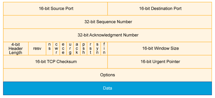
TCP segments are sent using IP packets. The TCP header follows the IP header, supplying information specific to the TCP protocol. This division of the headers allows host-level protocols other than TCP to exist. The fields of the TCP segment (illustrated in the figure) include the following:
- Source port: Number of the calling port (16 bits)
- Destination port: Number of the called port (16 bits)
- Sequence number: The sequence number of the first data octet in this segment, used to ensure correct sequencing of the arriving data (32 bits)
- Acknowledgment number: Next expected TCP octet (32 bits). A TCP connection is a reliable connection. The sending and receiving computers use acknowledgment to ensure that the data is sent and received as specified and that it arrives without errors and in the right order.
- Header length: Number of 32-bit words in the header (4 bits)
- Reserved: Set to 0 (6 bits, but some experimental specifications defined in RFCs are making use of some of those bits)
- Control bits: Contains nine 1-bit fields which is often referred to as a flag. Six of the flags are:
- URG: Indicates that the Urgent pointer field is significant.
- ACK: Indicates that the Acknowledgment field is significant. All packets, after the initial SYN packet, that are sent by the client should have this flag set.
- PSH: Push function. Asks to push the buffered data to the receiving application.
- RST: Reset the connection.
- SYN: Initiates a connection. Only the first packet that is sent from each end should have this flag set.
- FIN: No more data from sender. - Window: Number of octets that the device is willing to accept (16 bits). Windowing allows the sending computer to send out several packets without waiting to receive acknowledgment of those packets, which helps maintain the speed and reliability of the connection.
- Checksum: Calculated checksum of the header and data fields (16 bits)
- Urgent: Indicates the end of the urgent data (16 bits)
- Options: One currently defined maximum TCP segment size (0 or 32 bits, if any)
- Data: Upper-layer protocol data (varies in size)
TCP delivers these applications, among others:
- HTTP: HTTP is used by browsers to request web pages and by web servers to transmit the requested web page and web page components.
- HTTPS: HTTPS is a variant of HTTP that uses SSL or TLS to add a layer of security to data in transit.
- FTP: FTP is a full-featured application that is used for copying files by running a client application on one computer to contact the FTP server application on a remote computer. Files can be uploaded or downloaded using this application.
- Telnet: Telnet allows for an emulated terminal session to a remote device, often a UNIX host, router, or other network device. With an emulated terminal session, you can manage a network device as if you had a directly connected serial terminal. Telnet is useful only with systems that use character mode command syntax. Telnet is also a concern when in a secure environment as it sends its message in unencrypted cleartext, instead most organizations now use SSH for remote communications.
- SSH: SSH provides a secure way to access a remote computer. It provides secure encrypted data communications and strong authentication. SSH is widely used for managing systems and applications remotely.
- SMTP: SMTP is used by e-mail servers to exchange e-mail messages and by e-mail clients to send messages to an e-mail server. It works with POP3 and IMAP4 to enable e-mail clients to retrieve and store e-mail messages.
TCP Three-Way Handshake
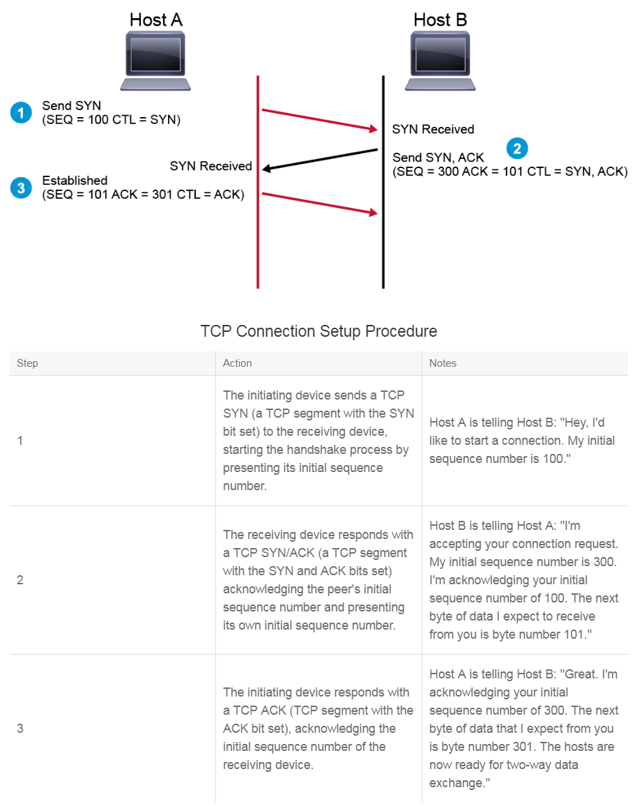
TCP requires a connection to be established between two end systems before data transfer can begin. TCP establishes the connection using a process that is called the three-way handshake. This process involves setting the SYN bit and ACK bit in the segments between the two devices. An important function that is performed during connection establishment is that the devices exchange their initial sequence numbers (ISNs). This number is used to track data bytes on this connection. The table below includes a simplified explanation of the three-way handshake process, which is illustrated in the figure.
A TCP connection is normally and gracefully terminated when each side of the connection closes its side of the connection independently. The following example provides a simplified description of the process:
- Host A sends a FIN (a TCP segment with the FIN bit set) to Host B to indicate that it wants to terminate the session.
- Host B sends an ACK (a segment with the ACK bit set) back to Host A, acknowledging that it received the FIN.
- Host B sends a FIN to Host A.
- Host A sends an ACK to Host B.
Introduction to the User Datagram Protocol
UDP is another widely used transport layer protocol. There are many UDP-based attacks, so a security analyst should have a good understanding of how UDP is intended to function and what a normal UDP datagram looks like. The security analyst must know what a normal UDP datagram looks like in order to recognize an abnormal UDP datagram that might contain hidden threats.
The security analyst should also understand the differences between TCP and UDP and hence recognize when one protocol or the other is appropriate when analyzing network communications.
UDP has the following characteristics:
- UDP operates at Layer 4 (the transport layer) of the OSI reference model.
- UDP = IP protocol number 17.
- UDP provides applications with efficient access to the network layer without the overhead of reliability mechanisms.
- Like IP, UDP is a connectionless protocol in which a one-way datagram is sent to a destination without advance notification to the destination device.
- UDP is capable of performing a very limited form of error checking. The UDP datagram includes an optional checksum value, which the receiving device can use to test the integrity of the data. In addition, the UDP datagram includes a pseudoheader. This pseudoheader includes the destination address. If the receiving device sees that the datagram is directed to an inactive port, it returns a message that the port is unreachable.
- UDP provides service on a best-effort basis and does not guarantee data delivery, because packets can be misdirected, duplicated, corrupted, or lost on the way to their destination.
- UDP does not provide any special features that recover lost or corrupted packets. These services, if they are required, are provided by the application layer process that uses UDP.
Using the UDP protocol services is analogous to using a postal service to send non-certified mail because it is not important if the mail is lost in transit or if a neighbor acknowledges receipt of the mail.
UDP delivers these applications, among others:
- TFTP: TFTP is a simple file transfer protocol. Most commonly, it is used to copy and install the operating system of a computer from the files that are located on a TFTP server. TFTP is a smaller application than FTP, and is typically used on networks for simple file transfer. TFTP contains its own error checking and sequencing number and, therefore, does not need reliability in the transport layer.
- SNMP: SNMP monitors and manages networks, the devices that are connected to them, and network performance information. SNMP sends PDU messages that allow network management software to monitor and control devices on the network.
- DNS: DNS translates, or "resolves" human-readable names of IP end systems into machine-readable IP addresses, which are necessary for routing. DNS can use either UDP or TCP. For name resolution, it usually uses UDP, which can be faster than TCP because there is no need to establish a connection. For messages whose sizes exceed the DNS protocol's limit and for operations to which reliable delivery is essential, DNS uses TCP.
- NTP: NTP is used to synchronize a computer to Internet time servers or other sources, such as a radio or satellite receivers or telephone modem services.
As illustrated in the figure, the length of a UDP header is always 64 bits.
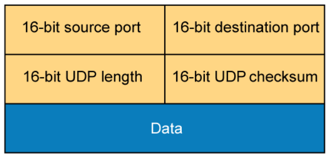
A UDP header consists of these fields:
- Source port: Number of the calling port (16 bits)
- Destination port: Number of the called port (16 bits)
- Length: Length of UDP header and UDP data (16 bits)
- Checksum: Calculated checksum of the header and data fields (16 bits)
TCP and UDP Ports
TCP and UDP use internal software ports to support multiple conversations between different network devices. The figure shows the range of port numbers available for each protocol and some of the corresponding applications.
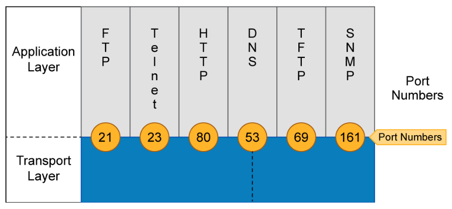
The IANA controls port numbers. Some frequently used applications have assigned port numbers, referred to as “well-known” port numbers. For example, Telnet normally uses port 23. If an analyst finds that a system is using the Telnet protocol on a non-standard port, it may warrant further investigation to determine why. The usage may be benign and justified, or it may be mischievous.
Well-known ports are assigned by the IANA and are numbered 1023 and below. These numbers are assigned to applications that are fundamental to the Internet and are defined in RFC 1700. Registered ports are listed by IANA and are numbered from 1024 to 49151. These ports are used for proprietary applications, such as Lotus Notes Mail. Ephemeral ports are assigned numbers between 49152 and 65535. These ports are assigned dynamically during a specific session.
Generally, a server has an application, often called a daemon, which listens on a well-known port. Client applications are dynamically assigned an ephemeral port to use by the client’s operating system. The client then uses this port to connect to the server which is listening on the well-known port.
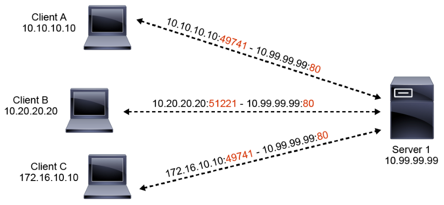
As shown in the figure below, a single host can have multiple sessions running at the same time, which are connected to one or more other computers. Each session must be distinguished from other sessions, which is done with a combination of IP addresses and port numbers. Take the example that is presented in the figure below. Server 1 is currently sustaining 3 sessions to three different hosts simultaneously. The server is a web server, listening on Port 80. The three sessions are distinguished by a 5-tuple: Local IP address, local port, protocol, remote IP address, remote port. Note that the remote ports that are used by Client A and Client C are identical, which can happen by coincidence, but the 5-tuple is unique for each session.
Address Resolution Protocol
To send data to a destination, a host on an Ethernet network must know the MAC address of the destination. ARP provides the essential service of mapping IP addresses to physical addresses on a network.
Note:
The MAC address is the unique identifier of the device. It is usually embedded in the hardware during manufacturing. The MAC address is also referred to as the hardware address or the physical address. The address is 48 bits long and is usually represented using hexadecimal notation. Groups of digits are commonly separated with colons, dashes, or periods. The following three example notations are common and equivalent: 54:EE:75:B1:6F:22, 54-EE-75-B1-6F-22, and 54EE.75B1.6F22.
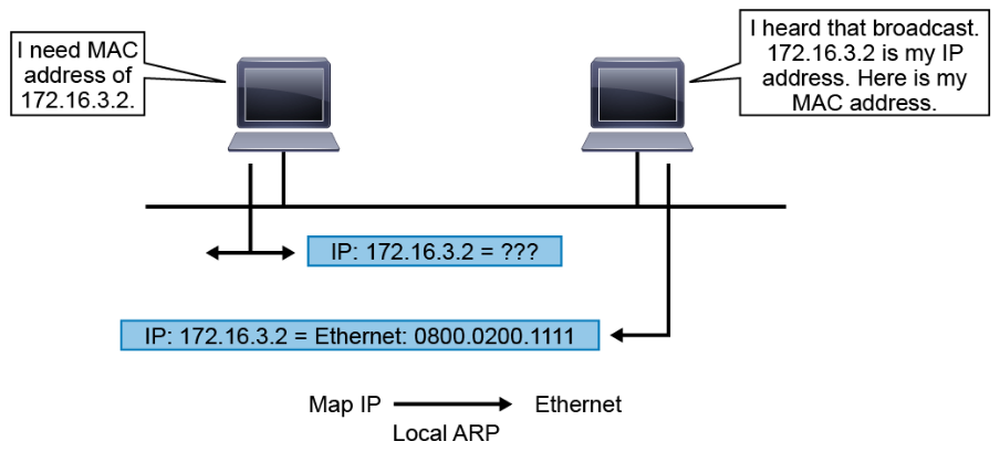
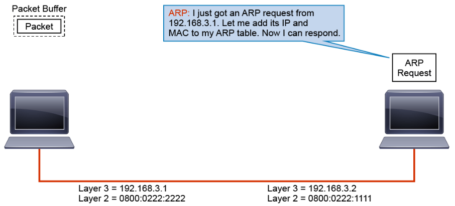
When a system knows the IP address of its peer but does not know the MAC address, it sends an ARP request. The ARP request specifies the known IP address and is broadcast on the local network. The broadcast is received by all devices on the Ethernet segment. When the target recognizes its own IP address by reading the contents of the ARP request packet, it responds with the required MAC address in its ARP reply. The address resolution procedure is completed when the originator receives the reply packet (containing the required MAC address) from the target. The originator then updates the table containing all the current bindings. This table is called the ARP cache or ARP table. The ARP cache is used to maintain a correlation between each IP address and its corresponding MAC address.
The bindings in the table are kept current by a process of aging out unused entries after a period of inactivity. The aging time is operating system dependent. Aging out ensures that the table does not contain information for systems that might be switched off or that have been moved.
The arp -a command can be used on both Windows and Linux devices to display the current state of the ARP table on the device.
Note:
The ARP table on the Windows system includes mappings for some multicast addresses, such as IGMP and LLMNR.
ARP operates between Layer 2 and Layer 3 of the OSI model. ARP messages are sent using Ethertype 0x0806. Ethertype is a two-octet field in an Ethernet header. Ethertype is used to indicate which protocol is encapsulated in the payload of an Ethernet Frame. Ethertype 0x0800 indicates an IPv4 payload, Ethertype 0x86DD indicates an IPv6 payload.
ARP is a necessary and fundamental service in the TCP/IP protocol suite. It does have some security shortcomings. One significant issue is that there is no validation of the ARP replies. Under the right circumstances, a system can produce fraudulent ARP replies, tricking victim systems into mapping the attacker’s MAC address to a different IP address, and causing the victim systems to send traffic that is intended for other systems to the attacker. The attacker can then become a man in the middle, and can monitor and manipulate the misdirected traffic before forwarding it to the valid destination.
Host-to-Host Packet Delivery Using TCP
A lot of complexity is involved in TCP/IP communications. The data link layer, networking layer, transport layer, and application layers must all coordinate. There are MAC addresses and IP addresses. ARP is used to bridge the gap between the two. TCP connections start with a three-way handshake, and then data is transmitted and acknowledged. The following example depicts all these processes in a detailed, step-by-step fashion.
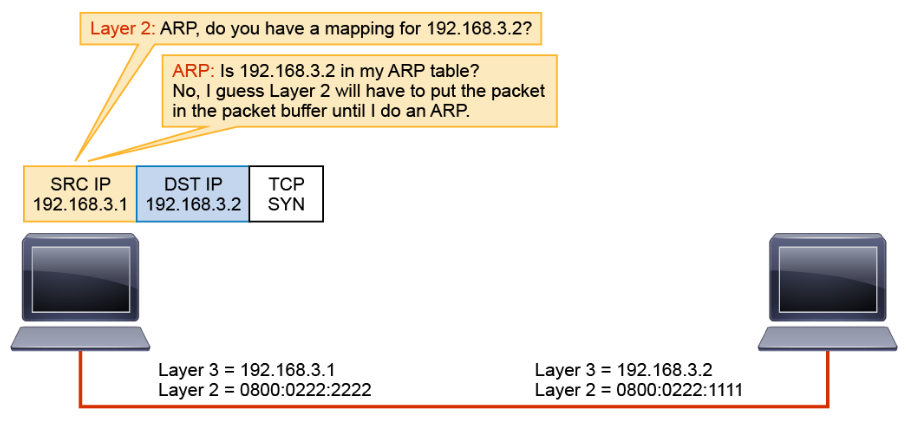
In this example, an application on the host with a Layer 3 address of 192.168.3.1 wants to send some data to the host with a Layer 3 address of 192.168.3.2. The application wants to use a reliable connection. The application requests this service from the transport layer.
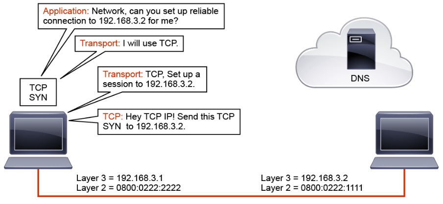
The transport layer selects TCP to set up the session. TCP initiates the session by passing a TCP header with the SYN bit set and the destination Layer 3 address (192.168.3.2) to the IP layer.
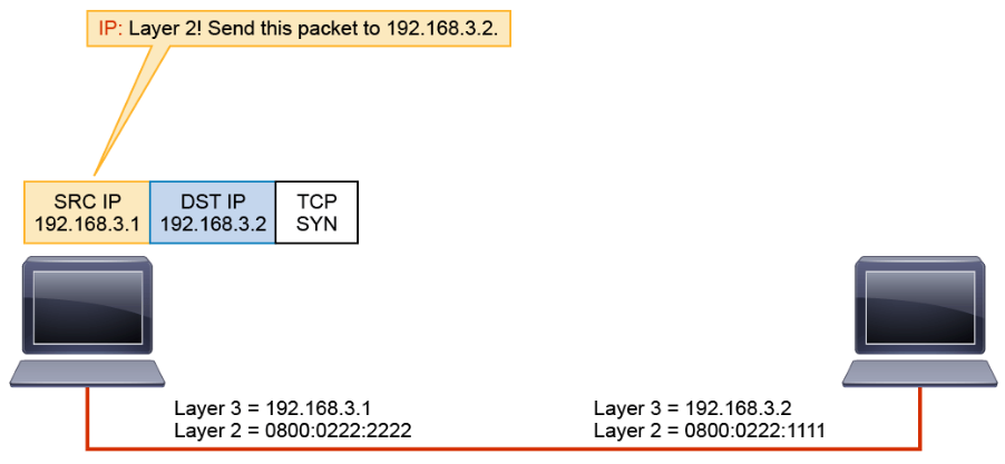
The IP layer encapsulates the TCP’s SYN in a Layer 3 packet by prepending the local Layer 3 address and the destination Layer 3 address that IP received from TCP. IP then passes the packet to Layer 2.
Layer 2 encapsulates the Layer 3 packet into a Layer 2 frame. To do this, Layer 2 needs to map the Layer 3 destination address of the packet to its MAC address by requesting a mapping from ARP.
ARP checks the ARP table. In this example, it is assumed that this host has not communicated with the other host, so there is no entry in the ARP table, which results in Layer 2 holding the packet until ARP can provide a mapping.
When host 192.168.3.2 receives the frame, it notes the broadcast address and strips the Layer 2 encapsulation.
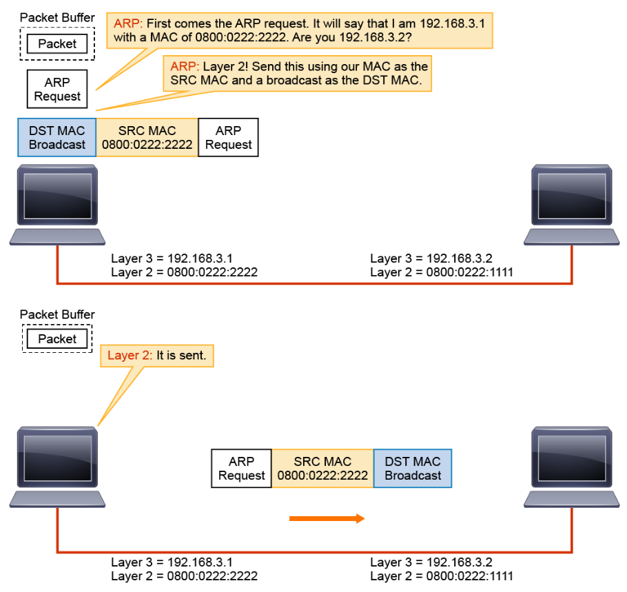
The ARP program builds an ARP request and passes it to Layer 2, telling Layer 2 to send the request to a broadcast address (all F hex values). Layer 2 encapsulates the ARP request in a Layer 2 frame. It uses the broadcast address that was provided by ARP as the destination MAC address, and the local MAC address as the source.
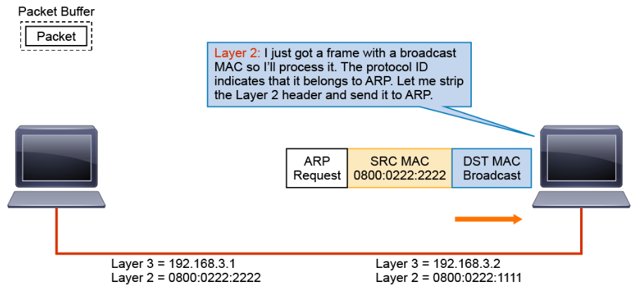
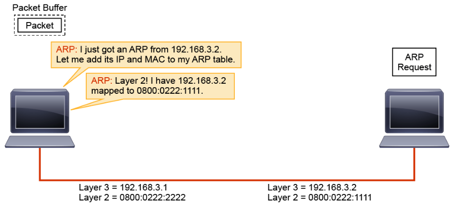
The remaining ARP request is passed to ARP.
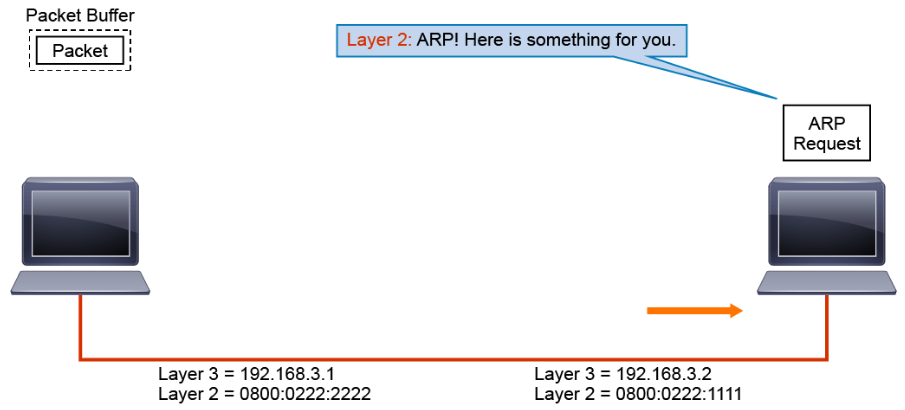
Using the information in the ARP request, ARP updates its table.
ARP builds a response and passes it to Layer 2, telling Layer 2 to send the response to MAC address 0800:0222:2222 (host 192.168.3.1).
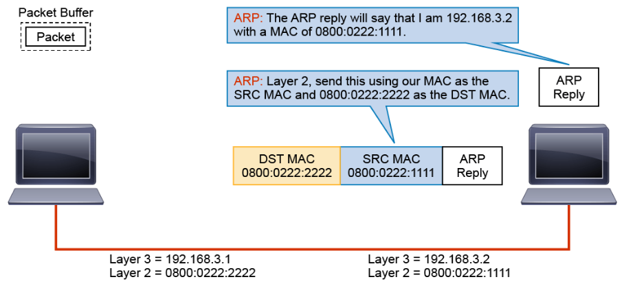
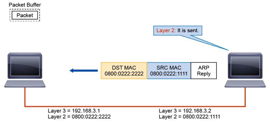
Layer 2 encapsulates the ARP in a Layer 2 frame using the destination MAC address that is provided by ARP and the local source MAC address.
When host 192.168.3.1 receives the frame, it notes that the destination MAC address is the same as its own address. It strips the Layer 2 encapsulation.
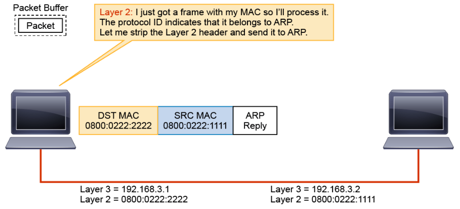
The remaining ARP reply is passed to ARP.
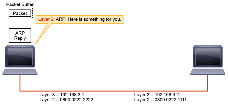
ARP updates its table and passes the mapping to Layer 2.
Layer 2 can now encapsulate the pending packet into a Layer 2 frame and send it to host 192.168.3.2
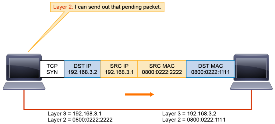
At host 192.168.3.2, the frame is passed up the stack where encapsulation is removed. The remaining PDU is passed to TCP.
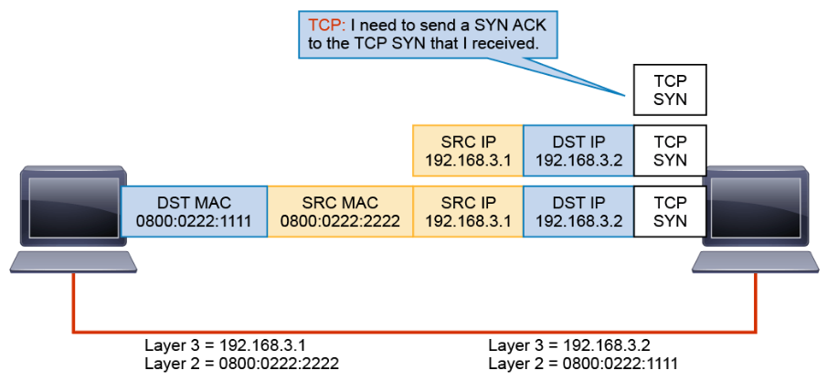
In response to the SYN, TCP passes SYN-ACK down the stack to be encapsulated.
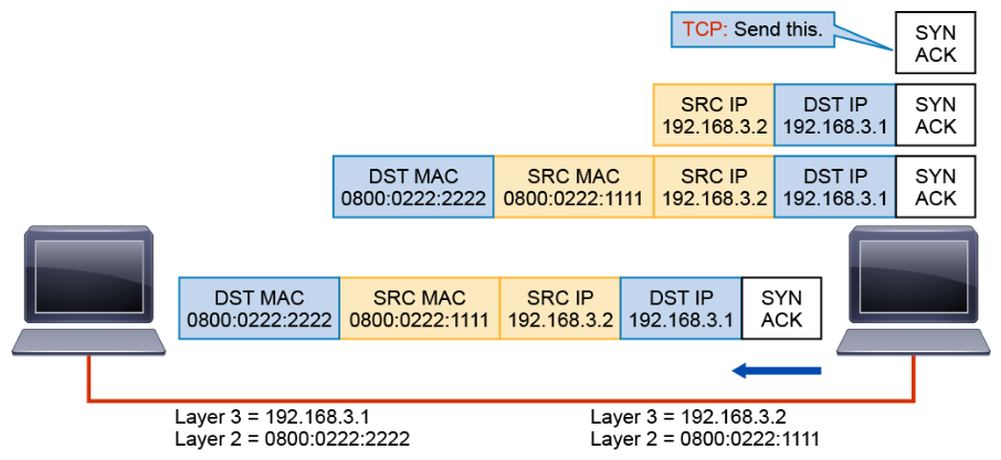
After the three-way handshake is completed, TCP can inform the application that the session has been established.
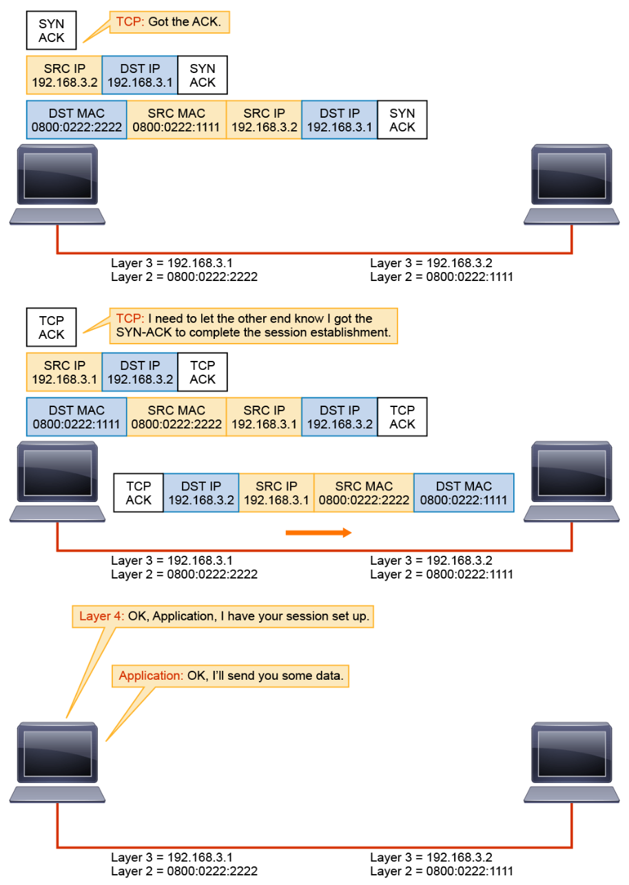
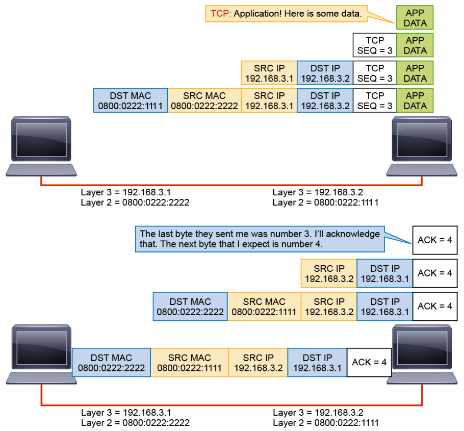
Now the application can send the data over the session, relying on TCP for error detection.
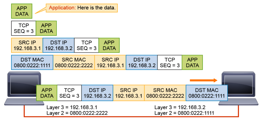
The data exchange continues until the application stops sending data.
Dynamic Host Configuration Protocol
Another basic IP service that is needed for host-to-host communications over an IP network is DHCP. DHCP is used to assign IP addresses automatically and to set TCP/IP stack configuration parameters, such as the subnet mask, default router, and DNS servers. DHCP is also used to provide other configuration information that is needed, including the length of time the address has been allocated to the host. DHCP consists of two components: a protocol for delivering host-specific configuration parameters from a DHCP server to a host, and a mechanism for allocating network addresses to hosts.
Note:
For certain types of servers such as DHCP servers and DNS servers, you should assign static (permanent) IP addresses.
Like ARP, DHCP is frequently used to carry out attacks, so it is important for a security analyst to understand how it works. Two of the most common DHCP attacks are the insertion of rogue DHCP servers and DHCP starvation. Rogue DHCP servers can be used to provide valid users with incorrect-configuration information to prevent them from accessing the network. DHCP starvation is exhausting the pool of IP addresses available to the DHCP server.
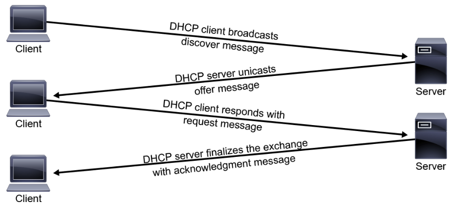
Using DHCP, a host can obtain an IP address quickly and dynamically. A range or pool of IP addresses is defined on a DHCP server. As hosts come online, they send broadcast requests for their IP configuration. The DHCP server selects an address from the pool and allocates it to that host. The address that is provided by the DHCP server is only leased to the host, requiring the host to periodically contact the DHCP server to extend the lease. This lease mechanism ensures that hosts that have been moved or are switched off for extended periods of time do not keep addresses from the pool that are not actually in use. The addresses are returned to the address pool by the DHCP server, to be reallocated as necessary. The normal process is shown in the figure below.
Four messages are exchanged during the process:
- The client sends a DHCPDISCOVER message.
- The server sends a DHCPOFFER message containing IP address and other IP configuration information.
- The client sends a DHCPREQUEST, which is an acknowledgement of the server's offer.
- The process ends with the server sending a DHCPACK, confirming the reservation for the client.
DHCP uses UDP port number 67 as the destination port of a server, and UDP port number 68 is used by the client. DHCP is the most widely deployed protocol for the dynamic configuration of systems over an IP network.
Domain Name System
DNS is another one of the basic IP services that are required for host-to-host communications over an IP network. It provides an efficient way to convert human-readable names of IP end systems into machine-readable IP addresses necessary for routing.
Like ARP and DHCP, DNS may be leveraged to carry out attacks. If DNS is compromised, threat actors can cause victims to establish connections with fraudulent, malicious systems. DNS can be used to covertly tunnel data from an internal compromised host out to systems controlled by the attacker. Because DNS is a UDP-based service, it can be leveraged in amplification DDoS attacks. To recognize, analyze, and accurately report on such attacks, security analysts need a solid understanding of DNS basics.
DNS is a globally distributed dynamic database that is used to translate names to IP addresses. DNS frees the users of IP networks from the burden of needing to remember the IP addresses. Without this freedom, the World Wide Web would not be as popular or as usable as it has become.
The translation process is accomplished by a DNS resolver. The DNS resolver could be a client application such as a web browser or an e-mail client, or a DNS application such as BIND sending a DNS query to a DNS server.
DNS uses TCP and UDP port 53. TCP port 53 is used for zone transfers when replicating the DNS database between different DNS servers. UDP port 53 is used for performing DNS queries from the clients.
Internet Control Message Protocol
ICMP is used to report errors and other information regarding IP packet processing back to the source. ICMP, which is documented in RFC 792, is best known for its use by the “ping” and “traceroute” programs on IP-enabled hosts, or devices. The ping utility sends ICMP echo request packets out to a destination host to test the IP connectivity to that destination host. Receiving an ICMP echo reply message indicates that the host can be successfully reached.
As a security analyst, it is important to understand ICMP. For example, in ICMP echo request packets, one should not expect to see a large data payload. Echo replies should also be paired with echo requests. If you see many ICMP echo request and reply packets with large payloads, or if you see an imbalance in echo request and echo reply numbers, you should suspect that something suspicious may be happening. An attacker may be tunneling data out using ICMP. ICMP tunneling is possible because RFC 792, which documents IETF’s rules governing ICMP packets, allows for an arbitrary data length for any type 8 (echo request), or type 0 (echo reply) ICMP packets.
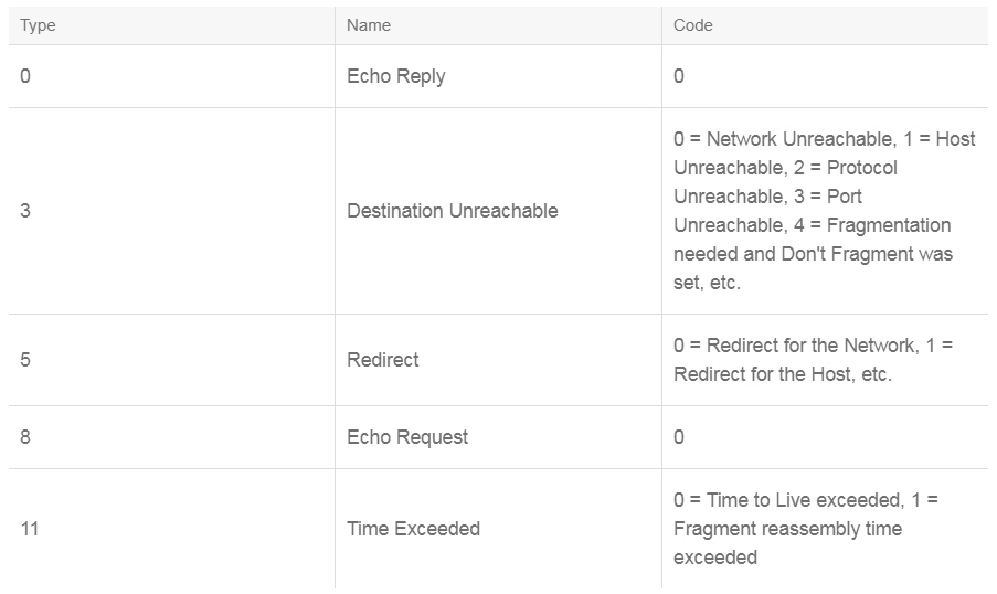
In addition to echo request and echo reply, ICMP has several kinds of useful messages, including destination unreachable, redirect, time exceeded, and so on.
Two reasons exist for why a destination might be unreachable. Most commonly, the source host has specified a nonexistent address. Less frequently, the router does not have a route to the destination.
Destination-unreachable messages include four basic types: network-unreachable, host-unreachable, protocol-unreachable, and port-unreachable.
- Network-unreachable messages usually mean that a failure has occurred in the routing or addressing of a packet.
- Host-unreachable messages usually indicate that the packet has been correctly routed to the destination network, but the destination is not active on that network.
- Protocol-unreachable messages generally mean that the destination does not support the transport-layer protocol that is specified in the packet.
- Port-unreachable messages imply that the destination is not listening on the specified TCP or UDP port.
An ICMP redirect message is sent by the router to the source host to stimulate more efficient routing if another router with a better path exists on the local subnet. The router still forwards the original packet to the destination.
An ICMP time-exceeded message is sent by the router if an IP packet’s TTL field reaches zero. The TTL field prevents packets from continuously circulating the internetwork if the internetwork contains a routing loop. The router then discards the original packet.
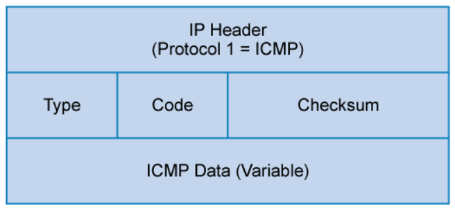
ICMP uses IP protocol number 1. ICMP messages are identified by the type field. Many of these ICMP types also use a code field to indicate different conditions. The table below shows a few of the common ICMP messages.
Packet Capture Using tcpdump
Packet capturing tools are used legitimately in networks today for network troubleshooting and traffic analysis. One such tool is tcpdump, a free, powerful, CLI-based tool for capturing and analyzing packet data. As a text-based utility, tcpdump can be run only from the command line of a computer. It can read live traffic from interfaces and prerecorded traffic from PCAP files, and it allows you to display TCP, IP, and other packets being transmitted or received over the network to which the computer is attached.
Packet capturing tools are valuable tools for security analysts. However, analysts should be aware of the fact that packet capturing tools are also valuable tools for attackers. Network management protocols (such as Telnet, FTP, HTTP, and SNMPv1 and SNMPv2) send data in cleartext. If an attacker can capture such management traffic, sensitive information such as usernames and passwords can be easily revealed.
Tcpdump is extremely common on Linux and UNIX hosts and on network infrastructure devices that are based on these operating systems. On the rare occasion that tcpdump does not come preinstalled, it is usually easy to download and install.
Windump, a Microsoft Windows variant of tcpdump, is also available. Tcpdump and windump can capture and display live network traffic from any directly connected interfaces, including traffic that is not addressed to the local machine. To capture traffic that is not destined for the local machine, the network card must be placed into a special mode, referred to as “promiscuous mode,” which causes the network card to interpret all traffic that it sees. Administrative or superuser permissions within the operating system are required to enter promiscuous mode. For this reason, tcpdump (and windump) must be run as the root user (or administrator user).
Tcpdump has machine-dependent limitations, which are based on the number of packets that it can process per second. If traffic arrives too quickly and cannot be saved in time, it is dropped by the kernel. Also, as with most packet capture software, tcpdump does not read data link layer data before the destination MAC.
In the following tcpdump live capture example, two tcpdump command options were used. The -i option defines the interface, which is eth0 in this case. The -n option specifies that addresses are displayed as IP addresses rather than as hostnames. Using the -n option is best for live captures. Without the -n option, the system attempts to look up the name of the host through DNS.
Use control+c to stop the traffic capture.
root@Kali:~# tcpdump -i eth0 -n
tcpdump: verbose output suppressed, use -v or -vv for full protocol decode
listening on eth0, link-type EN10MB (Ethernet), capture size 65535 bytes
10:06:57.246670 IP 192.168.28.1.137 > 192.168.28.255.137: NBT UDP PACKET(137): QUERY; REQUEST; BROADCAST
10:06:57.665021 ARP, Request who-has 192.168.28.128 (00:0c:29:66:4d:29) tell 192.168.28.1, length 46
10:06:57.665041 ARP, Reply 192.168.28.128 is-at 00:0c:29:66:4d:29, length 28
10:06:57.996116 IP 192.168.28.1.137 > 192.168.28.255.137: NBT UDP PACKET(137): QUERY; REQUEST; BROADCAST
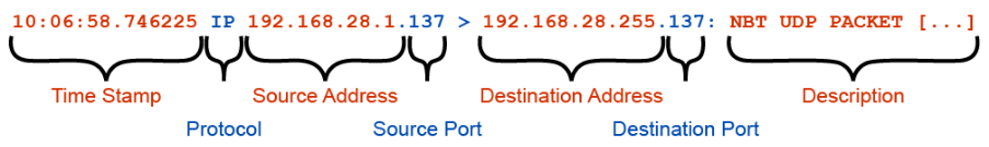
10:06:58.746225 IP 192.168.28.1.137 > 192.168.28.255.137: NBT UDP PACKET(137): QUERY; REQUEST; BROADCAST
5 packets captured
5 packets received by filter
0 packets dropped by kernel
root@Kali:~#
The figure below shows the different parts of the tcpdump output.
Other tcpdump command options:
The -w option specifies that tcpdump will write the network traffic to a PCAP file, specified here as “sample.pcap.” No output will occur while tcpdump is capturing to a file.
root@Kali:~# tcpdump -i eth0 -w sample.pcap

tcpdump: listening on eth0, link-type EN10MB (Ethernet), capture size 65535 bytes
7 packets captured
7 packets received by filter
0 packets dropped by kernel

root@Kali:~#
The -r option commands tcpdump to read from the same PCAP file that was created in the example here. In addition, the -x option is used to output the hexadecimal representation.
root@Kali:~# tcpdump -x -r sample.pcap

reading from file sample.pcap, link-type EN10MB (Ethernet)
06:52:39.152387 IP 192.168.28.1.137 > 192.168.28.255.137: NBT UDP PACKET(137): QUERY; REQUEST; BROADCAST
        0x0000:  4500 004e 7195 0000 8011 0eb9 c0a8 1c01
        0x0010:  c0a8 1cff 0089 0089 003a d504 e499 0110
        0x0020:  0001 0000 0000 0000 2046 4445 4c46 4a45
        0x0030:  4f45 4646 4543 4e45 4345 4d43 4143 4143
        0x0040:  4143 4143 4143 4142 4d00 0020 0001

root@Kali:~#
The -XX option outputs both the hexadecimal and ASCII representations. The ASCII representation is extremely useful when working with plaintext or human-readable data.
root@Kali:~# tcpdump -i eth0 -XX

tcpdump: verbose output suppressed, use -v or -vv for full protocol decode
listening on eth0, link-type EN10MB (Ethernet), capture size 65535 bytes
12:00:34.494200 IP 192.168.28.1 > 192.168.28.129: ICMP echo request, id 1, seq 5, length 40
        0x0000:  000c 2966 4d29 0050 56c0 0008 0800 4500  ..)fM).PV.....E.
        0x0010:  003c 691d 0000 8001 17d1 c0a8 1c01 c0a8  .<i.............
        0x0020:  1c81 0800 4d56 0001 0005 6162 6364 6566  ....MV....abcdef
        0x0030:  6768 696a 6b6c 6d6e 6f70 7172 7374 7576  ghijklmnopqrstuv
        0x0040:  7761 6263 6465 6667 6869                 wabcdefghi
1 packets captured
1 packets received by filter
0 packets dropped by kernel

root@Kali:~#
Tcpdump uses the PCAP (Packet Capture) library, or libpcap, to capture and filter network traffic. Similarly, windump requires the WinPcap libraries to capture and filter network traffic. Libpcap (and its Windows counterpart) uses a unique language to describe protocols and fields within the packets that it sees. This language is referred to as BPF (Berkley Packet Filter) syntax and has become the de-facto standard in many network utilities.
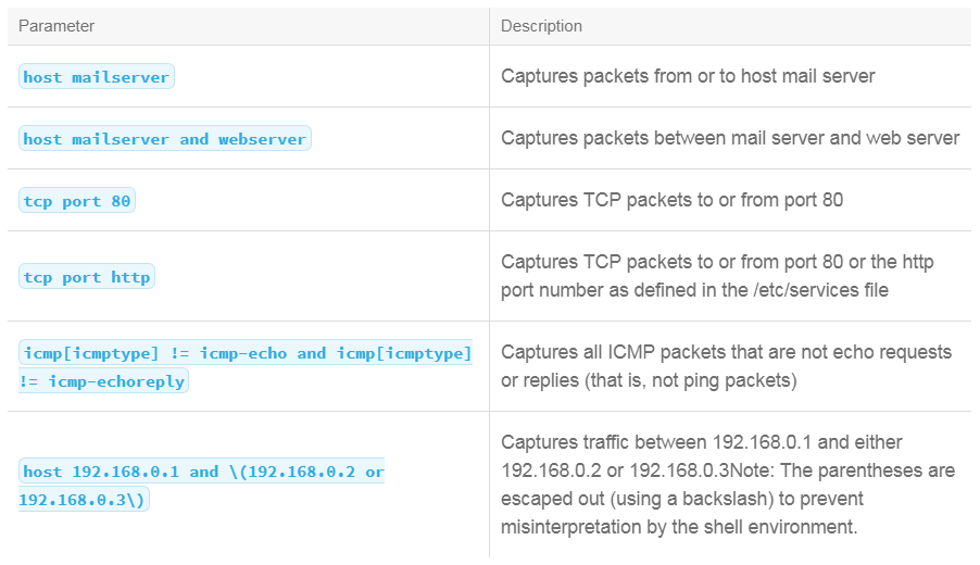
BPF syntax allows you to combine criteria to form a capture filter to be used within the tcpdump command:
host: Defines a specific hostnet: Defines a network, classful or classless, and can be combined withmask
-net 192.168.1.0
-net 192.168.1.0 mask 255.255.255.0
-net 192.168.1.0/24port: Specifies a specific portsrc: Source, can be combined with any typedst: Destination, can be combined with any typeand: Combines two filters; both must be trueor: Combines two filters; either must be truenot: Negates a filter (useful for ignoring designated traffic)ip: Filters, based on IPv4 packetsip6: Filters, based on IPv6 packetsarp: Filters, based on ARP trafficicmp: Filters, based on ICMP messagestcp: Filters, based on TCP segmentsudp: Filters, based on UDP datagrams
In the following example, the tcpdump command will capture traffic on the eth0 interface that matches IP address 10.1.1.2 and port 80 traffic. Examining the first three packets, you can see the TCP three-way handshake, where the first packet has the SYN flag, the second packet has the SYN and ACK flags, and the third packet has the ACK flag.
root@Kali:~# tcpdump -i eth0 port 80 and host 10.1.1.2

tcpdump: verbose output suppressed, use -v or -vv for full protocol decode
listening on eth0, link-type EN10MB (Ethernet), capture size 65535 bytes
18:42:18.923345 IP 172.16.1.2.54769 > 10.1.1.2.80: Flags [S], seq 2471859586, win 8192, options [mss 1460,nop,wscale 2,nop,nop,sackOK], length 0
18:42:19.022097 IP 10.1.1.2.80 > 172.16.1.2.54769: Flags [S.], seq 2637141512, ack 2471859587, win 8190, options [mss 1460], length 0
18:42:19.022326 IP 172.16.1.2.54769 > 10.1.1.2.80: Flags [.], ack 1, win 64240, length 0
18:42:19.425546 IP 172.16.1.2.54769 > 10.1.1.2.80: Flags [P.], ack 1, win 64240, length 461
18:42:19.510902 IP 10.1.1.2.80 > 172.16.1.2.54769: Flags [.], ack 462, win 10649, length 0

[output omitted]
BPF Syntax Examples:
Tcpdump is a powerful utility with a great deal of potential. Many resources are available to provide more detailed examples, and a more thorough explanation of the numerous command-line options.
Wireshark
During the incident investigation process, a typical task for an analyst is to perform packet capture and packet analysis. Wireshark is one of the common tools that is used to perform packet capture and analysis. Wireshark is available for Windows, Linux, and Macintosh systems.
Wireshark is designed to provide a graphical environment for packet analysis. Wireshark allows you to capture packets live and to open PCAP files that have been captured through another packet-capture device. As with tcpdump, there are limitations to the speed at which Wireshark can capture. It can take a considerable amount of time to process large files. Similar to tcpdump, Wireshark needs to run as Administrator or root to use promiscuous mode. To open a prerecorded PCAP file, a standard user account is acceptable.
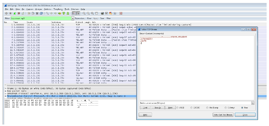
Below is an example of using Wireshark to examine a PCAP containing Telnet traffic. Telnet traffic is sent one character at a time in cleartext, that is why you won’t see the Telnet username and password in a single Telnet packet. Using the Wireshark Follow the TCP Stream feature, Wireshark will put all the data together so you will be able to see the Telnet username and cleartext password. The example below shows the username student and the password Cisco123!.
This section provides a high-level overview of Wireshark.
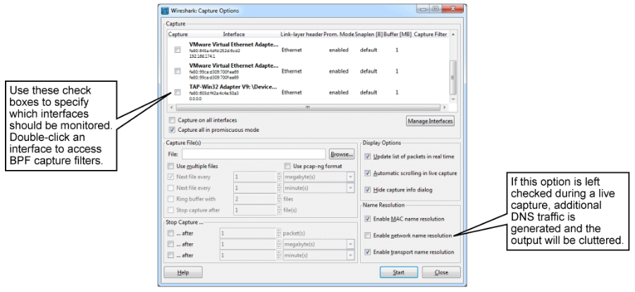
Clicking Capture Options from the main screen opens the Capture Options window. The Capture Options window allows you to select an interface if there are multiple interfaces, define filenames for output, set display options, end capture options, and define name-resolution options. If you are capturing traffic live, it is strongly recommended that you disable network name resolution by unchecking the Enable Network Name Resolution check box.
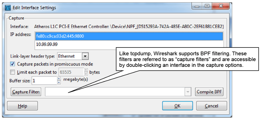
Double-click an interface to open the Edit Interface Settings window, which is shown in the figure below. This window allows you to limit the packet size, which sometimes may be required by your organization because of legal restraints. Also, you can set capture filters. Click the Capture Filter button to display examples of capture filters.
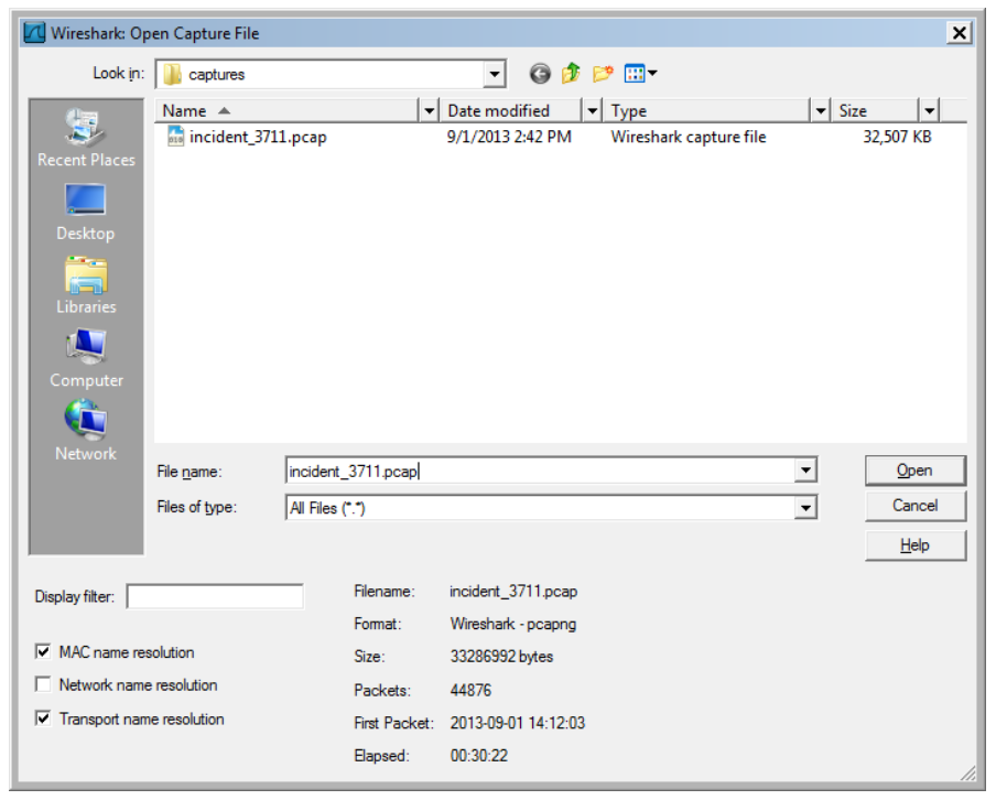
Alternatively, Wireshark can read data from a prerecorded PCAP file, using the File menu Open option. Note a brief summary at the bottom of the window of the PCAP file to be opened.
Once a packet capture has been started or a PCAP file has been opened, the main interface of Wireshark (shown below) is presented.
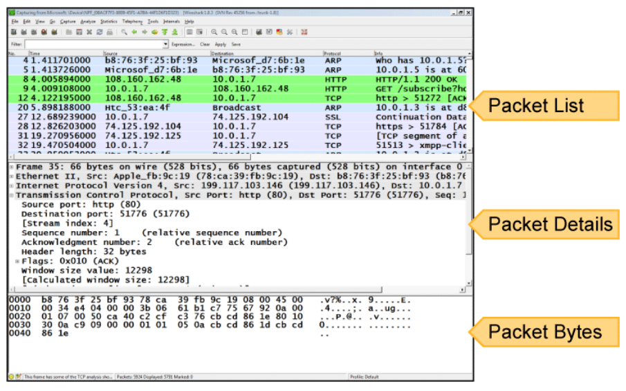
The main interface of Wireshark consists of three components:
- The packet list shows a complete list of packets within the current capture. Information about each packet is presented in customizable columns. By default, this information includes the packet number, time stamp, source address, destination address, protocol, and a summary field of protocol-specific information.
- The packet details list shows detailed information about the highlighted packet. Protocols within the packet are presented in expandable panes, with each field enumerated and explained. Some basic analysis is performed, such as translating port numbers to more human-readable names or displaying the human-readable flags in the Flags field.
- The packet bytes pane shows the raw bytes of the highlighted packet, starting at the link-level header. The output is divided into three columns: offset, hexadecimal representation, and ASCII representation.
In the main interface, analysts can quickly move around the capture to inspect packets of interest. Clicking a packet in the top third of the window, the packet list, alters the other two panes to show the details and bytes of the highlighted packet.
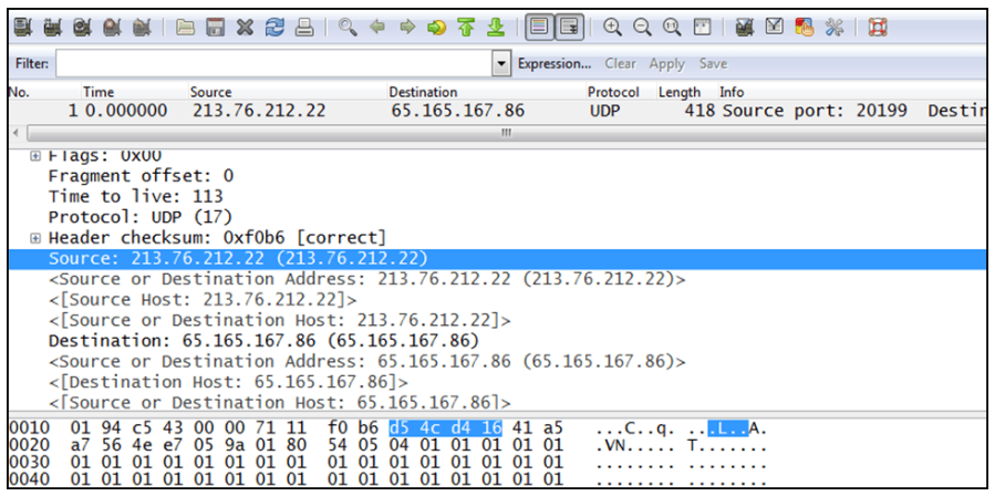
Expanding protocols within the packet details pane, analysts may find a field that interests them. As shown in the figure below, clicking a field highlights the relevant bytes in the packet bytes pane. This information not only helps analysts quickly learn about protocol structures, it also allows users who are more familiar with the protocol to quickly identify any inconsistencies.
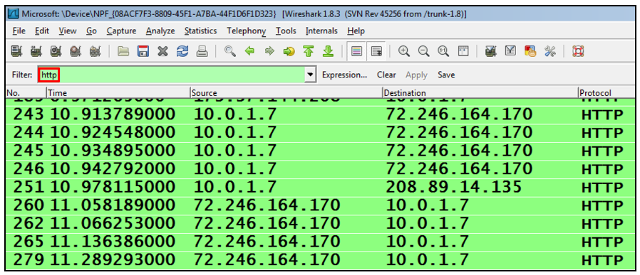
A brief mention of the role of filters is necessary at this point to distinguish the display filters at the top of the Wireshark window. In the example below, the http filter is applied to show HTTP traffic only. Do not confuse the display filters with the capture filters that were described with tcpdump. Tcpdump capture filters use BPF syntax. Wireshark display filters do not affect what is being captured, and they use proprietary syntax.